


Power supply designers are using flexible supply monitoring, sequencing, and adjustment circuits to manage their systems. This article discusses why and how.
The monitoring and control of a growing number of power-supply voltage rails has been vital for safety, economy, durability, and proper operation of electronic systems for many years - especially for systems employing microprocessors. Determining whether a voltage rail is above a threshold or within an operating window - and whether that voltage is powered on or off in the correct sequence with respect to the other rails - is crucial to operational reliability and safety.
Many methods exist to solve various aspects of this problem. For example, a simple circuit using a precision resistive divider, comparator, and reference can be used to determine whether the voltage on a rail is above or below a certain level. In 'reset generators', such as ADI's ADM803, these elements are combined with a delay element to hold devices - such as microprocessors, application-specific ICs (ASICs), and digital signal processors (DSPs) - in reset while powering up. This level of monitoring is adequate for many applications.
Where multiple rails need to be monitored, multiple devices (or multichannel comparators and their associated circuitry) are used in parallel, but increasing opportunities call for monitoring ICs that do more than simple threshold comparison.
For example, consider a common requirement for power-supply sequencing: an FPGA manufacturer may specify that the 3,3 V core voltage must be applied 20 ms before the 5 V I/O (input/output) voltage to avoid possible damage when the device is powered up. Meeting such sequencing requirements may be as crucial for reliability as keeping the device's supply voltage and temperature within specified operating limits.
Also, the number of power rails in many applications has increased dramatically. Complex, expensive systems, such as LAN switches and cellular base stations, commonly have line cards with 10 or more voltage rails; but even cost-sensitive consumer systems, such as plasma TVs, can have as many as 15 separate voltage rails, many of which may require monitoring and sequencing.
Many high-performance ICs now require multiple voltages. For example, separate core and I/O voltages are standard for many devices. At the high end, DSPs may require up to four separate supplies per device. In many cases, numerous multisupply devices can coexist in a single system that contains FPGAs, ASICs, DSPs, microprocessors, and microcontrollers (as well as analog components).
Many devices share standard voltage levels (such as 3,3 V), while others may require device-specific voltages. In addition, a particular standard voltage level may have to be independently furnished in numerous places. For example, separate analog and digital supplies, such as 3,3 VANALOG and 3,3 VDIGITAL, may be required. Generating the same voltage numerous times may be necessary to improve efficiency (eg, memory rails running at hundreds of amperes) or to meet sequencing requirements (3,3 VA and 3,3 VB needed by separate devices at different times). All of these factors contribute to the proliferation of voltage sources.
Voltage monitoring and sequencing can become quite complex, especially if a system must be designed to support a power-up sequence, a power-down sequence, and multiple responses to all possible fault conditions on the various supply rails at different points during operation. A central power management controller is the best way to solve this problem.
As the number of supply voltages increases, there is a much higher probability of things going wrong. The risk increases in proportion to the number of supplies, number of elements, and complexity of the system. External factors also add risk. If, for example, the main ASIC is not completely characterised at the time of the initial design, the power supply designer must commit to hardwiring voltage-monitoring thresholds and timing sequences that are subject to change as the ASIC specifications are developed. If the requirements change, the PC board may have to be revised - with obvious schedule and cost implications. Furthermore, the supply voltage specifications for certain devices may change during their development. In such circumstances, a way to readily adjust supplies would be useful to any central power-system manager. In fact, the flexibility to monitor, sequence, and adjust the voltage rails of such systems is a vital necessity.
Evaluating the robustness of the chosen fault protection and timing sequence can be a sizeable job, so a device that simplifies this process will speed up board evaluation and reduce time to market. Fault logging and digitised voltage and temperature data are useful features, both in the field and in all phases of design from early PCB development through prototype evaluation.
Basic monitoring
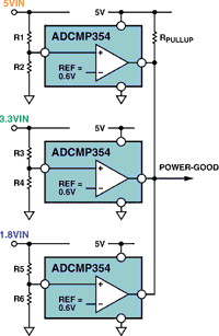
Figure 1 shows a simple method for monitoring multiple voltage rails using the ADCMP354 comparator and reference IC. An individual circuit is used for each rail. Resistive dividers scale the voltage rails down, setting an undervoltage trip point for each supply. All outputs are tied together to generate a common 'power-good' signal.
Basic sequencing
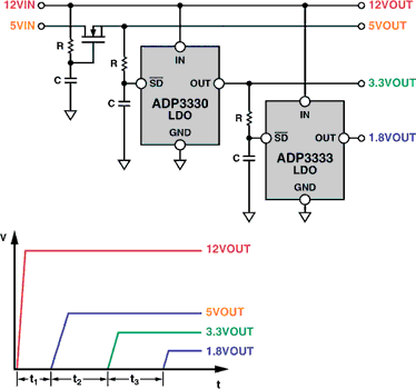
Figure 2 shows how basic sequencing can be implemented with discrete components, using logic thresholds instead of comparators. The 12 V and 5 V rails have been generated elsewhere. A time delay must be introduced to ensure that the system operates correctly. This is achieved by using a resistor-capacitor (RC) combination to slowly ramp the gate voltage on the n-channel FET in series with the 5 V supply. The RC values are chosen to ensure a sufficient time delay before the FET reaches its voltage threshold and begins to turn on. The 3,3 V and 1,8 V rails are generated with ADP3330 and ADP3333 low-dropout (LDO) regulators. The turn-on times of these voltages are also sequenced by RCs. No series FET is required, as the RC drives the shutdown (/SD) pin of each LDO. The RC values are chosen to ensure sufficient time delays (t2, t3) before the voltages on the /SD pins climb above their thresholds.
This simple, low-cost approach to sequencing power supplies uses little board area and is perfectly acceptable in many applications. It is suitable for systems where cost is the primary driver, the sequencing requirements are simple, and the accuracy of the sequencing circuit is not critical.
But many situations require more accuracy than is available with RC lag circuits. In addition, this simple solution does not permit faults to be dealt with in a structured way (eg, a 5 V supply failure will eventually bring down the other rails).
Sequencing with ICs
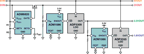
Figure 3 shows how the ADM6820 and ADM1086 power-supply-sequencing ICs can be used to accurately and reliably sequence power rails in a similar system. Internal comparators detect when a voltage rail goes above a precisely set level. The outputs are asserted after programmable turn-on delays, enabling the ADP3309 and ADP3335 regulators in the desired sequence. The thresholds are established by resistance ratios; the delay is established by a capacitor.
A wide variety of power-supply-sequencing ICs is available. Some devices have outputs that can be used to enable power modules directly, and numerous output configurations are available. Some include on-board charge-pump voltage generators. This is especially useful for low-voltage systems that need to sequence rails that are generated upstream but lack a high-voltage source, such as a 12 V rail, to drive an n-channel FET gate. Many of these devices also have enable pins to allow an external signal - from a pushbutton switch or a controller - to restart the sequence or shut the controlled rails off when required.
Integrated power system management
Some systems have so many power supply rails that discrete approaches that use a large number of ICs and set timing and threshold levels with resistors and capacitors become too complex and costly, and cannot provide adequate performance.
Consider a system with eight voltage rails that requires a complex power-up sequence. Each rail must be monitored for undervoltage and overvoltage faults. In the event of a fault, all voltages could be turned off, or a power-down sequence could be initiated, depending on the failure mechanism. Actions must be taken depending upon the state of the control signals, and flags must be generated depending on the state of the power supplies. Implementing a circuit of this complexity with discrete devices and simple ICs may require hundreds of individual components, a huge amount of board space, and a significant combined cost.
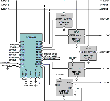
In systems with four or more voltages, it may make sense to use a centralised device to manage the power supplies. An example of this approach can be seen in Figure 4.
Centralised monitoring and sequencing
The ADM106x Super Sequencer family continues to use comparators, but with some important differences. Two comparators are dedicated to each input so that undervoltage and overvoltage detection can be implemented, thus providing windowed monitoring for the rails created by the ADP1821 and ADP2105 DC-DC converters and the ADP1715 LDO. An undervoltage fault is the normal condition of a rail before it powers up, so this indication is used for sequencing. An overvoltage condition usually indicates a critical fault - such as a shorted FET or inductor - and calls for immediate action.
Systems with higher supply counts usually have greater complexity, and thus have tighter accuracy constraints. Also, setting accurate thresholds with resistors becomes challenging at lower voltages, such as 1,0 V and 0,9 V. Although a 10% tolerance may be acceptable on a 5 V rail, this tolerance is generally insufficient on a 1 V rail. The ADM1066 allows input detector comparator thresholds to be set within 1% worst case, independent of the voltage (as low as 0,6 V) - and across the entire temperature range of the device. It adds internal glitch filtering and hysteresis to each comparator. Its logic inputs can be used to start the power-up sequence, shut down all rails, or perform other functions.
The information from the bank of comparators, fed into a powerful and flexible stage machine core, can be used for various purposes:
* Sequencing: When the output voltage of a recently-enabled supply comes into a window, a time delay can be triggered to turn on the next rail in the power-up sequence. Complex sequencing, with multiple power-up and power-down sequences, or vastly different sequences for power-up and power-down is possible.
* Timeout: If a rail that has been enabled does not come on as expected, a suitable course of action can be taken (such as generating an interrupt or shutting down the system). A purely analog solution would simply hang at that point in the sequence.
* Monitoring: If the voltage on any rail moves out of the preset window, a suitable course of action can be taken - depending on the rail that faulted, the type of fault that occurred, and the current operating mode. Systems with more than five supplies are often expensive, so comprehensive fault protection is crucial.
An on-board charge pump is used to generate approximately 12 V of gate drive, even if the highest available system voltage is as low as 3 V, allowing outputs to directly drive series n-channel FETs. Additional outputs enable or shut down DC-DC converters or regulators, allowing an output to internally pull up to one of the inputs or the on-board regulated voltage. The outputs can also be asserted open-drain. Outputs may also be used as status signals such as 'power good' or 'power-on' reset. Status LEDs can be directly driven from the outputs if required.
Supply adjustment
In addition to monitoring multiple voltage rails and providing a solution for complex sequencing, integrated power management devices, such as the ADM1066, also provide the tools to temporarily or permanently adjust individual rail voltages. The voltage output of a DC-DC converter or regulator can be altered by adjusting the voltage at the trim or feedback node of that device. Typically, a resistive divider between the output and ground of the module sets a nominal voltage at the trim/feedback pin. This, in turn, sets a nominal output voltage. Simple schemes involving switching extra resistors or controlling variable resistances in the feedback loop will alter the trim/feedback voltage and hence adjust the output voltage.
The ADM1066 is equipped with digital-to-analog converters (DACs) to provide direct control over the trim/feedback node. For maximum efficiency, these DACs do not operate between ground and a maximum voltage; instead they operate across a relatively narrow window centred on the nominal trim/feedback level. The value of an attenuation resistor scales the incremental change in the output of the power module with each LSB change of the DAC. This open-loop adjustment provides margin-up and margin-down levels equivalent to those obtained by digital resistance switching in the reference circuit, and will adjust the output to a similar accuracy.
The ADM1066 also includes a 12-bit ADC to measure the supply voltage, so a 'closed-loop' supply adjustment scheme can be implemented. With a given DAC output setting, the voltage output of the power module is digitised by the ADC and compared with the target voltage in software. The DAC can then be adjusted to calibrate the voltage output as closely as possible to the target voltage. This closed-loop scheme provides a very accurate method for supply adjustment. With a closed-loop method, the accuracy of the external resistors is completely irrelevant. In Figure 4, the output voltage of DC-DC4 is adjusted by one of the on-chip DACs.
There are two primary uses for the supply adjustment scheme. The first is the concept of 'margining' the supplies, ie, testing the system's response to operating its supplies at the margins of the specified supply voltage range of the equipment. Manufacturers of datacom, telecom, cellular infrastructure, server, and storage area network equipment are required to test their systems strenuously before shipping to their end customers. All of the power supplies in the system will be specified to operate with a certain tolerance (eg, ±5%, ±10%). Margining allows all the supplies on board to be adjusted to the high-end and low-end of the tolerance range, with tests performed to ensure correct operation. A centralised power management device with supply-adjustment capability can be used to do this margining test while minimising the need for the extra components and PCB area required to perform a function that is only needed once - during the margin test at the manufacturer's test site.
Four-corners testing, ie, testing across the operational voltage and temperature range of the equipment, is often required, so the ADM1062 integrates temperature-sensing and readback in addition to closed-loop power-supply margining circuitry.
The second use for the supply adjustment scheme is to compensate for system supply variations in the field. There are many causes for such variation. Short term, it is quite common for the voltages to change slightly as the temperature changes. Longer term, some of the component values may drift slightly over the life of the product, which can result in voltage drift. The ADC and DAC loops can be activated periodically (eg, every 10, 30, or 60 seconds) in conjunction with a software calibration loop to keep the voltages where they should be.
Flexibility
The ADM1066 has on-board nonvolatile memory, allowing it to be reprogrammed as many times as necessary, while the sequencing and monitoring needs of the system evolve during the development process. This means that the hardware design can be completed early in the prototype process, and optimisation of the monitoring and sequencing can be done as the project progresses.
Functions such as digital temperature and voltage measurement simplify and speed up the evaluation process. Margining tools will allow adjustment of the voltage rails during the development cycle. So in a situation where a key ASIC, FPGA, or processor is also in development, and the supply-voltage levels or sequencing requirements are in a state of flux as new silicon revisions are shipped, a simple adjustment can be performed via the software GUI. Thus, the power management device can be reprogrammed in a few minutes to take the changes into account, without the need to physically change components on the board or - worse still - redesign the hardware.
Conclusion
The increasing number of voltage rails and the emergence of power supply sequencing have increased the demands on the power designer in all sorts of devices and systems - everything from notebook PCs, set-top boxes, and automotive systems, to servers and storage, cellular base stations, and Internet-routing and switching systems. More stringent testing procedures, new levels of information gathering, and quick and simple programmability are also of interest, especially in mid- to high-end systems. For increased robustness and reliability, and the addition of these vital new features, there are many new power management integrated circuits available to help solve these problems safely, efficiently, and with minimum board area, while reducing time to market.


© Technews Publishing (Pty) Ltd | All Rights Reserved
 printer friendly version