


SEPIC (single ended primary inductance converter) topology offers a constant output voltage over a wide input voltage range. The input voltage can be lower, equal or higher than the output voltage.
The need for two inductors is often described as a disadvantage in application notes. However, in the case of coupled inductors on the same core, one can save board space and additionally, the 'zero-input-ripple-current' condition can be reached. This condition is very interesting, because the generated EMI noise is minimised and so the input filtering can be simplified.
SEPIC
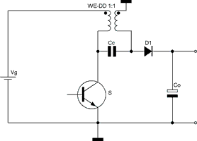
A SEPIC is a combination of Buck and Boost regulator topologies which are coupled through the Capacitor Cc (see Figure 1). At turn-on, Cc will charge to Vg. When power-switch S turns on, the left end of Cc is connected to ground and its right-plate voltage -Vc (= -Vg) is applied to the undotted end of the secondary winding. The voltage at the secondary side has the same polarity that the Vg source (at the converter input) is applying to the primary. Each winding attempts to induce the same voltage into the other. During the off time of S, D1 conducts, applying the output voltage (plus diode drop) to the primary winding through the secondary. This voltage induced across the primary winding happens to be the same voltage applied to it by the algebraic addition of the input source and Vc in series with VOUT + VD1.
For an ideal transformer, this would cause an over-constrained electrical indeterminacy, like connecting current sources in series or voltage sources in parallel.
What will the winding currents actually be in the coupled case?
Remember that the leakage inductance values (Llp/Lls) of the SEPIC or Cuk [A Cuk converter is a type of DC-DC converter that has an output voltage magnitude that is either greater than or less than the input voltage magnitude, with an opposite polarity] transformer windings are much smaller than the mutual (magnetising) inductance, M.
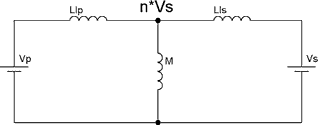
The secondary voltage source, Vs, induces n · Vs into the primary, as shown across the magnetising inductance. For the interesting case, Vs = Vp = Vg, if the turns ratio, n, is increased slightly from unity, by 1/k (where k < 1 is the coupling coefficient between windings), then the voltage induced by Vs will increase the voltage at the centre node to n · Vg, thereby 'bootstrapping' Llp. Because the voltage at each end of Llp is the same, its inductance is effectively infinite.
Consequently, all variations in magnetising current, (through M) due to a varying Vg is supplied from the secondary winding source. By symmetry, setting n = k causes the secondary-winding current to become constant while the primary source supplies the magnetising-current variations. This effect can be desirable because (for n = 1/k), it results in constant (DC) primary current. Noisy switching current does not appear at the converter input, but is diverted instead to the secondary winding. However, typical values of k are slightly less than one, and turns ratios of nearly 1:1 may not be easy to wind.
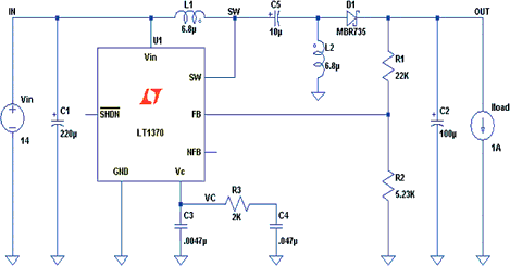
Figure 3 shows an example of a SEPIC application.
To get a better knowledge about the differences of a SEPIC regulator we shall analyse the solution with two (uncoupled) inductors and a coupled inductor solution, like the WE-DD series from Würth Elektronik.
Duty cycle
For continuous mode, the duty cycle is:
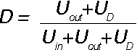
With UD being the diode forward voltage.
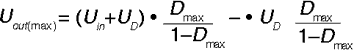
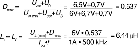
If the input voltage Uin is the same as the output voltage, the duty cycle will be around 50%. The maximum possible output voltage is limited by the maximum duty cycle (D) of the regulator and is:
Inductance value and currents
Example: Output current 1 A, output voltage 6,5 V and input voltage range 6-20 V at switching frequency f = 500 kHz.
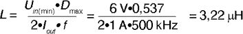
Calculate minimum inductance:
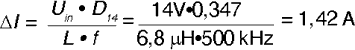
Chosen inductor value = 6,8 μH. The ripple current at 14 V input is then:
The maximum currents through L1 and L2 can be calculated to:
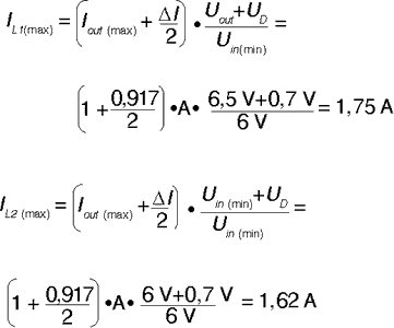
Hence the saturation current of the inductor should be around 2 A for stable operation.
Coupled inductor operation (WE-DD):
If the inductors are built on one core, theoretically the inductance can be lower and be set to L1=L2=L:
But in practical design one will choose the same value as for uncoupled inductors to achieve lower ripple currents in general. Additionally, by coupling on the same core, the total ripple current will then be smaller than that in uncoupled inductors.
Simulation
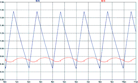
Simulations were done using the free SwitcherCAD III/LTSpice software tool from Linear Technology. See Figures 4 and 5.
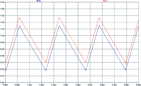
In both inductors the ripple current is around 1,5 A. This causes: higher core loss in core material; and EMC noise problems if traces and current loops are too big. In the case where SEPIC-inductors like the WE-DD were used, a dramatic decrease of ripple current is found.
In Figure 5, the ripple current on the output is still 1,5 A p-p , but the input ripple current is reduced to only 100 mA p-p. This can also be shown and verified by measurements. This low ripple current through L1 minimises the filtering components in input filtering stage and saves costs in the total solution.
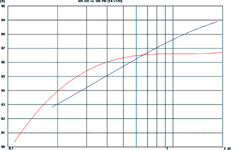
Efficiency
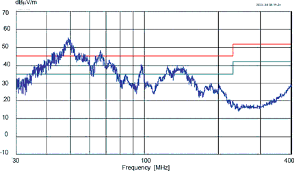
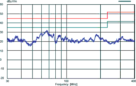
The efficiency measurement shows in Figure 6, that the use of coupled inductors did increase the total efficiency of the SEPIC by around 1,5 to 2% in the high output current range. Additionally, EMC noise problems are minimised by using coupled inductors. A practical measurement shows the total effect in Figures 7 and 8.
Conclusion
SEPIC-regulators will become more and more important in battery-operated systems. By special design of the power inductors to coupled versions, the noise in input current will be minimised and EMC problems reduced. At the same time, by using coupled inductors more efficiency can be obtained from the circuit.
For more information contact Stephen Delport, Hi-Q Electronics, +27 (0)21 595 1307, [email protected]
| Tel: | +27 21 595 1307 |
| Email: | [email protected] |
| www: | www.hi-q.co.za |
| Articles: | More information and articles about Hi-Q Electronics |


© Technews Publishing (Pty) Ltd | All Rights Reserved
 printer friendly version