


Nordic Semiconductor′s nRF24Z1 is an ideal transceiver for linking wireless headphones to portable music players. Nordic has now released a headphone reference design to demonstrate the feasibility of the nRF24Z1 in this application.
The Nordic nRF24Z1 single-chip 2,4 GHz, RF transceiver is a wireless CD quality audio streaming device suitable for headphones communicating with CD-, MP3- and Mini Disk-players. The nRF24Z1 maintains 4 Mbps bandwidth to stream true 'lossless' digital audio. The nRF24Z1 uses adaptive frequency hopping to avoid clashes with other devices operating in the 2,4 GHz band. The chip is manufactured using low-cost 0,18 μm CMOS fabrication, and is supplied in a 36-pin, 6 x 6 mm QFN package.
Nordic has produced a reference kit for design engineers featuring functionality similar to that of proprietary wireless headphones. The reference kit demonstrates the feasibility of the nRF24Z1 in music players and provides comprehensive guidance for the implementation of a nRF24Z1-based design.
The hardware and published design files aid customers who want to design their own products based on the nRF24Z1. The design files need only small alterations (for example, to the PCB form factor and placement of the user interface buttons on the PCB) to convert them to production-ready files.
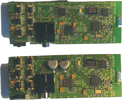
The reference design comprises an audio transmitter (ATX) PCB, an audio receiver (ARX) PCB and a daughterboard used for in-system programming and debugging. The system is controlled by a microcontroller on the ATX board. Both the ATX and ARX PCBs feature a user interface comprising six pushbuttons and an LED. The user interface can be easily modified.
In this article we consider how to avoid crosstalk, positioning and impedance matching of the antennas for optimum reception and reliable pairing.
Avoiding crosstalk
The nRF24Z1 is a radio transceiver using packet-based transmission. Consequently, the chip will constantly toggle between transmit and receive modes. The current draw in each mode is different and this can give rise to a voltage ripple on the power supply. If the ripple transfers to the analog audio element of the design (ie, the ADC, DAC and CODEC devices), a persistent 250-430 Hz hum will be heard through the earphones.
To avoid this contamination, when the nRF24Z1 is used in combination with ADC, DAC and CODECs it must be considered part of the digital element. It is very important to avoid power supply noise generated by the nRF24Z1 (and other digital circuitry) from reaching the analog supply pins and reference voltage pins of the ADC, DAC and CODEC. Star-routing directly from a low-noise supply source (for example, a linear voltage regulator) is highly recommended. The nRF24Z1 should have its own power supply line from the supply source. The ADC, DAC and CODEC should also have their own separate digital and analog supply lines. In some designs an LC filter (comprising serial inductor and shunt capacitor) on the analog supply line to the ADC, DAC and CODEC could also be required.
A power supply distribution strategy based on star-routing from a linear voltage regulator with supply decoupling for the nRF24Z1, ADC and DAC devices has been implemented on the ATX and ARX boards of the reference design. This includes a power supply distribution strategy, supply decoupling, PCB layout and other important design issues for the nRF24Z1, plus the illustrated use of a Wolfson Microelectronics ADC (WM8951L) and DAC (WM8711L) in accordance with the relevant datasheets for each device.
Good ground layout is just as important as the power supply distribution strategy to ensure the best possible performance both from the nRF24Z1 and the ADC and DACs. The ATX and ARX PCBs use a two-layer board and available areas of each layer are covered in the ground plane. The ground planes of each layer are connected by via holes.
Antenna design
The ATX and ARX PCBs use a Fractus FR05-S1-N-0-102 chip SMD antenna. The antenna has been positioned according to the recommendations given in the Fractus antenna user manual: 'Wireless Headsets' (document AN_FR05-S1-N-0-102).
Environmental factors such as the shape of the PCB, area of ground plane, proximity to housing, housing material and proximity to the user can affect the antenna impedance matching and radiation properties. Changing one or more of these parameters in an application will change the antenna impedance and may require re-matching the antenna and receiver for good performance.
When designing with Nordic's nRF devices, the initial antenna impedance matching should be based on the standard 50 Ω matching network as described in the product specification. The antenna impedance is measured with the antenna placed in its normal position and with the application operating in its natural environment. If the measured antenna impedance deviates significantly from 50 Ω, extra matching components must be added in between the standard 50 Ω matching network and the antenna input to make the antenna act as a 50 Ω load. In most cases, antenna impedance can be matched by adding a Pi network (ie shunt C or L - series C or L - shunt C or L) in-between Nordic's standard 50 Ω matching network and the antenna input.
Vector network analysers are widely used for antenna impedance and voltage standing wave ratio (VSWR) measurements. After establishing the impedance value, the graphical aid method of a Smith chart is an effective way of designing the added impedance matching network. The ATX and ARX boards use a 1,5 pF shunt capacitor to ground. This was needed for optimal impedance matching of the Fractus antenna when operating in the 2,4 GHz band.
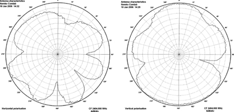
Figure 2 shows the ATX board measured antenna radiation patterns with horizontal and vertical polarisation. Often, practical designs produce radiation patterns that are not omni-directional and this is the case with the reference design. Consequently, great care must be taken when placing the antenna in a headphone design to ensure that ATX and ARX PCB antennas point towards each other in most user situations. Therefore follow the antenna manufacturers guidelines closely when placing the antenna and additional matching circuitry.
Reliable pairing
Both the ATX and ARX PCBs have six pushbuttons and one power on/off switch. While for simplicity, the reference design's ATX and ARX PCBs each use two AAA batteries and a hard On/Off switch, a typical application would consist of a rechargeable battery and charging electronics with a soft power On button.
There are three different ways to implement a soft power On button when using the nRF24Z1. These options are: soft power On on the ATX PCB only; soft power On on the ARX PCB only, and soft power On on both boards. The third option consumes more battery power than the other options. Much of the reference design depends on this choice.
When the boards are powered up they broadcast on an initial address. This address must be chosen carefully so that it is not compatible with a competitor's product. Once the ATX and ARX are both switched on and the user presses and holds the Play button, the ATX will generate a random private address for both devices for the time the power is on. This means that at power up, any ATX may pair with any ARX within a product family. (A product family is made up of ATX and ARX devices that all share a common initial broadcast address, DAC chip, buttons definition and power saving scheme.)
After one set of ATX and ARX has paired on a private address, other devices in the same area may be paired too. If the ATX pairs with an unwanted device, switching both ATX and ARX off and back on will result in a new pairing.
The reference design uses dynamic pairing at every power up. Consequently, if battery Off is selected on one device, battery Off must also be selected on the other in order for them to pair again. This is because if devices are paired and then one is turned off the other will retain the private address and not return to broadcasting the initial address before it is switched off and then back on. The reference design uses this methodology because it is impossible to detect if loss of signal is due to the partner being turned off or being moved temporarily out of range.
It is possible to add a reset button to the nRF24Z1 that will have the same effect on the device as power cycling. However, this has not been implemented on the reference design.
nRF24Z1 reference kit
The nRF24Z1 reference kit comprises: reference design audio transmitter (ATX) PCB; reference design audio receiver (ARX) PCB; daughterboard used for in-system programming and debugging; flat flexible cable (FFC) with connector; Nordic's EEPROM programmer USB dongle; USB cable.
| Tel: | +27 21 555 8400 |
| Email: | [email protected] |
| www: | www.rfdesign.co.za |
| Articles: | More information and articles about RF Design |


© Technews Publishing (Pty) Ltd | All Rights Reserved
 printer friendly version