


As IC packages get smaller and smaller, new thermal management problems arise. Although these new devices often dissipate the same, or even more power than earlier generations, it is much more difficult to get rid of the heat generated. Good thermal evaluation becomes essential in order to ensure system reliability.
Some simple calculations can help designers to predict the thermal performance of an IC. Lab testing should then be used to verify the results of the calculations, to provide a higher level of confidence.
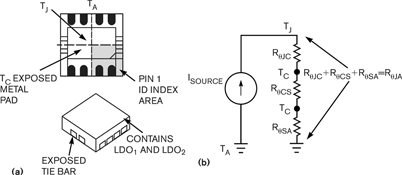
The example chosen here uses a dual low-drop-out regulator (LDO) in an 8-pin, dual flat no-lead (DFN8) package. Dual LDOs convert a single battery input voltage to two lower output voltages with approximately twice the power dissipation of a single LDO. The DFN8 package also has a lower thermal resistance than its larger counterparts.
The DFN8 package is shown in Figure 1a. For example, with an input voltage of 4,2 V, the first regulator in the package (LDO1) provides a typical output of 2,8 V at 300 mA, while the second regulator (LDO2) generates a typical output of 1,8 V at 150 mA. The power dissipation for the device is 780 mW and the maximum allowable steady-state junction temperature is 125°C.
The thermal resistance, junction-to-ambient (RθJA), of the DFN8 package is specified in the data sheet as 41°C/W. This figure is defined by the four-layer test method described in the JEDEC JESD51-5 and JESD51-7 standards. The test conditions include a four-layer board, copper thickness of 57 g on the outer layers and 28 g on the inner layers.
A first-order thermal calculation can be made by using the elements of the model shown in Figure 1b. Here, power is the 'current source,' temperature is the 'voltage,' and thermal resistance is a 'resistor.' The definitions of the variables are ISOURCE = power in watts, TJ = chip junction temperature in °C, TC = device case temperature in °C, TA = ambient temperature in °C, RθJC = thermal resistance from chip junction to device case in °C/Watt, RθCS = thermal resistance from device case to copper ground plane (PC board) in °C/Watt, and RθSA = thermal resistance from device copper ground plane to ambient (air) in °C/Watt.
If the dual device dissipates 780 mV, the rise in temperature at the junction above ambient is TJ(RISE) = 32°C (using RθqA equal to 41°C/W). The reliability requirement limits the maximum ambient temperature to (125°C-32°C) or 93°C.
It is possible to produce a layout for this dual LDO circuit that only requires a two-layer board. However, this produces very different thermal results. For example, consider a board with a 1,59 mm FR4 substrate and 28 g copper traces, with the traces on the top layer and the copper ground plane on the bottom. Using this board, the junction-to-ambient thermal resistance (RθqA) is 78°C/W.
Measurements of the thermal response of the circuit when it is implemented on a two-layer board shows that the rise in temperature, compared to the four-layer with vias implementation, increases from 32°C to 59°C. Under these conditions, the maximum ambient temperature is (125°C-59°C) or 66°C. This temperature difference is primarily due to lack of internal layers and vias directly into the copper plane, as defined by the JEDEC standard. This example shows that, although data sheet specifications are accurate, the physical implementation of the circuit on the PCB can make a significant difference to the thermal performance of the device.
| Tel: | +27 11 923 9600 |
| Email: | [email protected] |
| www: | www.altronarrow.com |
| Articles: | More information and articles about Altron Arrow |
| Tel: | +27 11 458 9000 |
| Email: | [email protected] |
| www: | www.electrocomp.co.za |
| Articles: | More information and articles about Electrocomp |
| Tel: | +27 21 421 8292 |
| Email: | [email protected] |
| www: | www.futureelectronics.com |
| Articles: | More information and articles about Future Electronics |
| Email: | [email protected] |
| www: | |
| Articles: | More information and articles about Tempe Technologies |


© Technews Publishing (Pty) Ltd | All Rights Reserved
 printer friendly version