


Today′s high performance computing systems are power hungry and consume more each year. Overall growth in IT demand and increasing energy costs outstrip the improvements in performance per device, resulting in ever-higher electricity bills. ″In fact,″ says Sun′s Dave Douglas, ″the cost of the power to operating servers will soon surpass the cost to buy them.″
Companies are making major changes to control costs: for example Google, Yahoo and Microsoft have invested in building new data centres along the Columbia River to be as close as possible to hydro-electric power, minimising electrical transmission loss and the cost of the electricity.
The traditional 'AC-to-12 V d.c. silver box, followed by 12 V-to-1,x V sync buck converter' power supply designs have run aground in terms of system power density and efficiency due to a combination of distribution bus losses and fundamental restrictions in topology performance as processor voltages reach sub-volt levels.
Higher voltage (48 V or 350/380 V) bus voltages reduce distribution losses, but usually mean the addition of an extra stage or stages to get down to the processor voltages, which increase size and may lower conversion efficiencies. A new approach is clearly needed for the next generation of servers, and one solution - factorised power architecture (FPA) - offers the promise of optimising efficiency, thus reducing power costs, while minimising the area used for power delivery.
The benefits of the new approach can be demonstrated by comparing efficiency and space requirements for a typical mid- to high-end data processing system comprised of one or more blocks of eight microprocessors, each running at 1,2 V and 100 A for a total load of 960 W per block. The system is fed via an AC-to-48 V d.c. front end with a 208 V a.c. input.
Baseline system performance (efficiency and size)
A typical AC - 48 V d.c.-1,x V d.c. system (Figure 1), using components and subsystems that are in mass production today, has an overall 67% efficiency from AC to point-of-load (POL), meaning that for our 960 W load, the system draws approximately 1430 W from the AC line. The difference of 470 W is lost as heat, which compounds the existing thermal management problem, requiring better heat sinking and airconditioning systems, which further increase the running costs of the data centre.
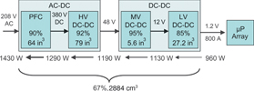
The system that has been analysed uses a common topology, with the AC-to-48 V d.c. unit comprising of a standard bridge, filter and boost PFC, generating 380 V, and then a two-transistor forward converter with diode rectification to 48 V d.c. The 48-to-1,2 V conversion assumes four 48 V: 12 V unregulated bus converters in ¼-brick format followed by a 4- or 5-phase voltage regulator module (VRM) or a voltage regulator-down (VRD) to the processor (Figure 1).
The power density for a typical commercially-available AC-to-48 V d.c. front ends would be 610 mW/cm³. In 800 W to 1500 W designs, the PFC stage (including AC-bridge and input EMI filter) normally occupies around 40% of the whole converter. The PFC stage and HV (380 V-to-48 V) DC-DC stage can then be estimated based on the output power level of each stage.
Factorised power architecture
FPA uses three flexible building blocks known as 'V·I Chips' to redefine the boundaries of each conversion stage and enable higher densities and efficiencies. The bus converter module (BCM) has a narrow-range input, and is an unregulated, high efficiency bus converter offering isolation and voltage transformation using a zero current switching-zero voltage switching (ZCS-ZVS) sine amplitude converter (SAC). Both high voltage (up to 384 V) and medium voltage (48 V) input versions are available. The pre-regulator module (PRM) is a unique ZVS high efficiency buck-boost converter. The final building block is the voltage transformation module (VTM). The VTM is a wide range 48 V input, high efficiency voltage transformation unit using the ZCS-ZVS SAC. The VTM works in combination with a PRM to give a low voltage output down to 0,82 V.
FPA building blocks enable greater flexibility, scalability and efficiency in power system design. The SAC in the BCM runs at an effective frequency of 3,5 MHz, using unique planar magnetics for high power conversion in a small package, and achieves power density of more than 62,02 W/cm³, offering substantial reductions in size over other technologies.
In this article, we focus on the performance of the 48 V-to-processor section. Using a PFC front end (eg, FE375) upstream to create an HV bus and then HV BCM converters, we can produce 1200 W at 48 V with 95,5% efficiency: a significant improvement on a conventional front end.
Traditional VRMs/VRDs rely on the tried and trusted synchronous buck PWM converter. As processor voltages fall towards 1 V and below, however, the duty cycle to generate this voltage from 12 V reaches 12:1 (Synch FET:Control FET). Moving to a 48 V bus may not produce the anticipated improved efficiency due to the challenges presented by the extremes of duty cycle, coupled with the higher FET voltage requirements and subsequent higher RDS(ON).
FPA enables the separation of the PWM's regulation and voltage transformation stages into two separate blocks. The PRM generates a factorised bus, typically controlled to 48 V, and the VTM (a current multiplier with very low output impedance up to 1 MHz) provides high-efficiency voltage transformation directly at the processor or point of load (POL). For the 960 W load in our example, eight VTMs are used (one per 100 A processor). As PRM V·I chips are capable of much higher powers (up to 320 W each), only four are needed, and they are simply arranged in parallel with connected outputs.
FPA delivers several substantial benefits. The inherent high efficiency results in significant power savings. The physical separation of PRM and VTM allows the PRM to be placed at a distance from the VTM, with 94% reduction in distribution losses (W/Ω) as a 48 V rather than 12 V bus can be used. Additionally, the separation enables minimised space requirements, because only the VTM is required to be at the processor which minimises the board area required and the losses due to high current traces. A further unique benefit of FPA is that the high bandwidth bi-directional transformation within the VTM enables the removal of bulk capacitance from the processor and its replacement by a much smaller (typically 1/1000) capacitance at the factorised bus. This major reduction in bulk capacitors substantially reduces the space required for the power supply system. Owing to the VTM's high bandwidth and low Q characteristic, the ceramic bypass capacitor requirement at the POL is also greatly reduced as it only needed to support dynamic response within a time scale of 1 ms. Finally, FPA offers outstanding transient response, meeting the rapidly fluctuating power demands of modern processors and ICs (see Figures 2 to 4).
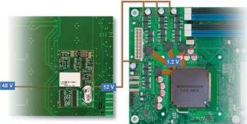
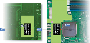
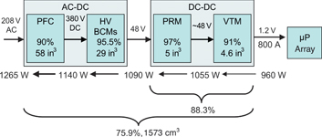
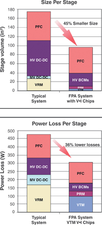
Figure 5 compares the power loss, size and efficiencies per stage of a typical solution with one using FPA. Using V·I Chips within an FPA solution increases overall efficiency by 8,6% and requires 45% less space than the original design. In practice FPA can achieve further size and efficiency gains could be achieved with improved connectors and distribution system.
Conclusion
Factorised power architecture using V·I Chips greatly improves system efficiency and power density. This offers a substantial financial benefit, as the power drawn from the AC-line is the major cost to data centres. The system will run cooler as losses are reduced by 36%, allowing other components to be more efficient and increasing reliability. Further energy and costs savings are made because 36% less heat must be removed by airconditioning, which itself is inefficient. Taking into account operating duty cycles and the cost of energy per kWh, the FPA system saves the end user more than 24 Euro per processor, per year with the added advantage of reducing CO2 emissions.






© Technews Publishing (Pty) Ltd | All Rights Reserved
 printer friendly version