


Selecting the proper integrated circuit (IC) for a power-supply application may seem like an easy task. However, as newer consumer electronics come out that require multiple voltage rails, the task becomes more complex.
To select the correct IC(s) for the job, many factors such as cost, solution size, power source, duty cycle, and required output power must be weighed. These factors must be ranked by importance and the power supplies selected accordingly.
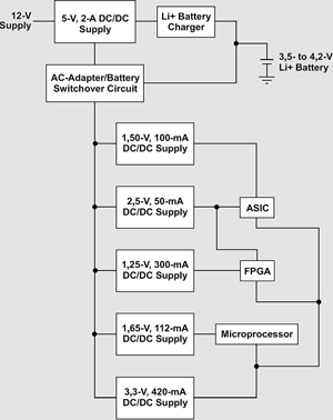
In this article, we will determine the best solution for the application shown in Figure 1. Our example application is portable, requires the lowest possible battery consumption and a small form factor, and operates from a single-cell Li-ion battery that is charged whenever the 12 V supply is available. We want to keep the cost to a minimum; but this can be sacrificed for space considerations, which are the most important requirements, followed by the highest efficiency possible to extend battery life.
Selecting the best topology
First, let us examine the power requirements of each rail to determine what kind of DC-DC converter should be used (ie, inductive switcher, linear regulator, or charge pump). Inductive switchers are usually the best choice for highest efficiency. The inductive switcher circuits require a switching element, rectifier, inductor, and input and output capacitors. For many applications, the solution size can be reduced by choosing a device where the IC switching element and rectifier are internal. These circuits have typical efficiencies ranging from 80 to 96%, depending on the load.
Switching converters usually require more space due to the size of the inductor and are generally more expensive. The switching converter also causes electromagnetic interference (EMI) radiation from the inductor and noise on the output due to the switching. Low-dropout linear regulators (LDOs) step down DC voltages by dropping the input voltage across a pass element. The benefit of this topology is that it requires only three parts (pass element and input/output capacitors). LDOs are usually a cheaper solution and are much less noisy than inductive switchers. The device input current is equal to the load current, so the efficiency of the solution is equal to the output-to-input voltage ratio. The drawback of this solution is the low efficiency for high input-to-output voltage ratios. All of the power is dissipated by the pass element, which means that an LDO is not an ideal solution for high-current applications where the input-to-output difference is large. These high-power applications require heat sinking, which increases the solution size.
Charge pumps step up/down or invert DC voltages using 'flying' capacitors as storage elements and use internal switches to connect the capacitors in such a way as to perform the desired DC-DC conversion. Charge pumps are generally cheaper than inductive switchers and do not emit EMI, but the output ripple is usually greater than that of inductive switchers. Charge pumps are limited in their output power, and the transient response is limited to the rate at which the flying capacitors can charge. Additionally, efficiency is usually very low in applications where the input voltage is near the output voltage.
To further reduce the solution size, many multi-output ICs are available. These ICs usually contain internal MOSFETs and require a minimum of external components. These ICs alone may be more expensive, but the savings gained by the reduction of external parts that must be placed during production will, in many cases, offset the higher cost.
What topology should we use?
Due to the space constraints of this application, LDOs would be our best choice. However, this is not always possible due to power dissipation and efficiency constraints. Beginning with the 5 V, 2 A rail, it is clear that we should choose a switching converter. The power dissipated by an LDO, in this case 14 W is excessive. For this rail, an inductive step-down converter is the best choice.
Next we move on to the battery charger. This battery is charged from the 5 V rail. Our application is for a single-cell Li-ion battery that has a charging voltage of 4,2 V. With the space constraints of our application, a linear charger is a good choice. The charging efficiency is not as much of a concern because the only time this device will operate is when the 12 V power adapter is available. However, when selecting the peak charge current of a battery deeply discharged to 3 V, we must take care to limit the thermal dissipation of the device.
* For the 1,50 V rail, either a switching step-down converter or an LDO would be acceptable. With the latter, our efficiency would be in the 25% range and would require an input current of 100 mA. If we substitute a switching step-down converter, we could get efficiencies higher than 90%, which requires an input current of 30 mA. There are many very small switching-converter solutions that can supply the required output power, so the size increase over an LDO circuit is not appreciable. To maximise battery life, the step-down converter is a better choice.
* For our 2,5 V rail, again, either topology is acceptable. Due to the low current requirements and lower input/output differential, an LDO is the best choice for the smallest size.
* For our 1,25 V rail, a switching converter is the best choice. With the high (300 mA) load requirement and the large input/output differential, an LDO would dissipate too much power and is too inefficient.
* For the 1,65 V rail, again, either topology is acceptable. Using the same logic as for the 1,50 V case, we could choose a switching converter; but other factors discussed later require that this be an LDO.
* For the final 3,3 V rail, a switching converter is the best choice due to the large output current required.
Selecting the best IC(s) for the job
Taking into consideration our size and cost constraints, the chosen ICs should be as highly integrated as possible. All of the selected ICs contain internal MOSFETs. This saves on solution size as well as on production costs. In addition to a reduced bill of material, the reduced component count reduces the cost to assemble each board for further cost savings. There are also multi-output ICs available that decrease our solution size even further.
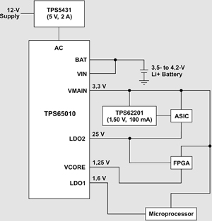
If we start again with the 5 V rail, the best solution for this is TI's TPS5431. Its wide input range (5,5 to 23 V) will accept our 12 V, ±10% input. The TPS5431 also provides up to 3 A with an adjustable output voltage down to 1,2 V. The switching MOSFET and the compensation components are integrated, and the 95% efficiency meets our battery-power demands. The device comes in the SO-8 package for a very small solution size.
Proceeding to the battery charger, we have several choices. The bq24010, a small battery charger IC in the 3 x 3 mm QFN package, is a good choice. Its solution size is very small and requires only three external components, but there is a better solution for our application. The TPS65010 is a power- and battery-management IC for Li-ion-powered systems. This device is an excellent fit for our application, as it integrates two switching converters (VMAIN and VCORE), two LDOs (LDO1 and LDO2), and a single-cell Li-ion battery charger. In addition to these rails, the IC also eliminates the need for a switchover circuit when the 12 V power adapter is connected.
In our application, VMAIN powers the 3,3 V rail, VCORE powers the 1,25 V rail, LDO1 powers the 1,65 V rail, and LDO2 powers the 2,5 V rail. Using the TPS65010 drastically reduces our solution size as well as the external component count.
The remaining 1,50 V rail can be powered from a stepdown switcher such as the TPS62201. This device comes in a five-lead SOT-23 package and requires only three external components (input/output capacitors, inductor, and two feedback resistors). This translates to a very small solution size. To increase efficiency, the input of this device should be connected to the 3,3 V VMAIN output of the TPS65010.
The final solution, based on the preceding discussion, is shown in Figure 2.
No I²C interface available?
If our application did not have an I²C interface available, we would not be able to use the TPS65010. In this situation, TI's TPS75003 would be useful. It contains two 3 A switching DC-DC step-down converters as well as one 300 mA LDO. This adjustable output device would integrate the three highest current rails. The 1,25 V and 3,3 V rails would be supplied by the switching converters. The LDO would supply the 1,65 V rail because of the lower current requirement. The remaining 2,5 V rail is easily supplied by a small LDO circuit. The TPS71525, which comes in an SC-70 package and is stable with ceramic output capacitors, provides a very small solution size. A larger but less expensive solution is the TPS76925 to power the 1,65 V rail. The TPS76925 control circuitry requires a minimum equivalent series resistance on the output for stability, so this may interfere with the size constraints.
Calculating the system efficiency difference
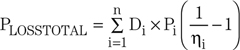
For this discussion, we have assumed that all of the voltage rails are on 100% of the time, which is rarely the case. Sometimes, where an inductive switcher would typically be used, an LDO may be an acceptable choice to minimise solution size. We can determine which to use by calculating the efficiency difference between each topology. Using the percentage of time that an output is enabled (the duty cycle), we can determine the effect of each rail on the total solution efficiency. First, the effective total output power is calculated by summing up the effective power for each rail:
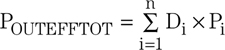
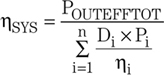
where Pi is the output power from one output rail and Di is the duty cycle for the same rail. Next, we calculate the power lost by each rail:
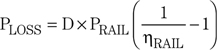
We then sum up the power loss for all of the rails to get the total power loss:
where hi is the efficiency of the individual output rail. We then calculate the effect of each rail on the overall system efficiency:

By summing all of the rail system efficiencies or by using the following equation, we can determine the total system efficiency:
For example, if the 3,3 V, 420 mA rail we previously decided should be powered from a switching converter was enabled for only 10% of the operation time, then using an LDO instead of a switcher would result in a drop of less than 0,75% in overall efficiency. This is illustrated more clearly in Table 1.
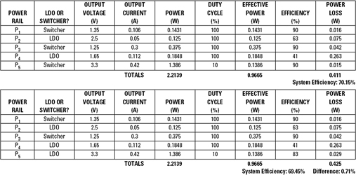
If the 3,3 V output was on all the time, using an LDO instead of an inductive switcher would reduce the overall efficiency by nearly 4%. These two cases are clearly extremes but illustrate how the duty cycle affects the overall efficiency. As the duty cycle for an output increases, the calculation of solution size versus efficiency must be examined to determine the optimal solution.
Conclusion
Selecting between the many different options available for DC-DC conversion can be a daunting task. Requirements such as available space, available input power, output power, duty cycle, and cost all must be examined to choose the best solution. We can start by ranking the requirements by importance, then select the topology for each output based on the requirements. Finally, we can choose the most cost-effective solution for each output. Following these simple steps should take the difficulty out of power-supply design.


© Technews Publishing (Pty) Ltd | All Rights Reserved
 printer friendly version