


During the mid 1970s, the maintenance-free lead-acid battery was developed that could operate in any position. The liquid electrolyte was transformed into moistened separators and the enclosure was sealed. Safety valves were added to allow venting of gas during charge and discharge.
Two designations of sealed lead-acid batteries have emerged: the sealed lead-acid (SLA), also known as 'Gelcell', which serves predominantly in wheeled mobility, and the large valve regulated lead-acid (VRLA), which is used for stationary applications. This article focuses on the SLA.
The SLA is not subject to memory. Leaving the battery on float charge for a prolonged time does not cause damage. The battery's charge retention is best among rechargeable batteries. Whereas the NiCd self-discharges 40% of its stored energy in three months, the SLA self-discharges the same amount in one year. The SLA is relatively inexpensive to purchase but the operational costs can be more expensive than the NiCd if full cycles are required on a repetitive basis.
The SLA does not lend itself to fast charging - typical charge times are 8 to 16 hours. The SLA must always be stored in a charged state. Leaving the battery in a discharged condition causes sulphation, a condition that makes the battery difficult, if not impossible, to recharge.
Unlike the NiCd, the SLA does not like deep cycling. A full discharge causes extra strain and each discharge/charge cycle robs the battery of a small amount of capacity. This wear-down also applies to other battery chemistries in varying degrees. To prevent the battery from being stressed through repetitive deep discharge, a larger SLA battery is recommended.
The SLA provides 200 to 300 discharge/charge cycles. The primary reason for its relatively short cycle life is grid corrosion of the positive electrode, depletion of the active material and expansion of the positive plates. These changes are most prevalent at higher operating temperatures. Applying charge/discharge cycles does not prevent or reverse the trend.
Among modern rechargeable batteries, the lead-acid battery family has the lowest energy density, making it unsuitable for handheld devices that demand compact size. In addition, performance at low temperatures is poor. The high lead content makes the SLA environmentally unfriendly if carelessly disposed.
Charging the lead-acid battery
The charge algorithm for lead-acid batteries differs from nickel-based chemistry in that voltage-limiting, rather than current-limiting, is used. The charge time of a SLA is 12 to 16 hours. With higher charge currents and multistage charge methods, the charge time can be reduced to 10 hours or less. SLAs cannot be charged as quickly as nickel or lithium-based systems.
A multistage charger applies constant-current charge, topping charge and float charge (Figure 1). During the constant-current charge, the battery charges to 70% in about five hours; the remaining 30% is completed by the slow topping charge. The topping charge lasts another five hours and is essential for the well-being of the battery. If never completely saturated, the SLA would eventually lose its ability to accept a full charge and the performance of the battery is reduced. The third stage is the float charge, which compensates for the self-discharge after the battery has been fully charged.
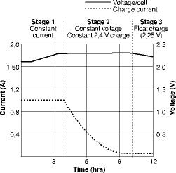
The charge voltage threshold is critical. A typical voltage limit is from 2,30 V to 2,45 V. If a slow charge is acceptable, or the room temperature may exceed
30°C, the recommended voltage limit is 2,35 V/cell. If a faster charge is required, and the room temperature will remain below 30°C, 2,40 to 2,45 V/cell may be used. Table 1 compares the advantages and disadvantages of the voltage settings.
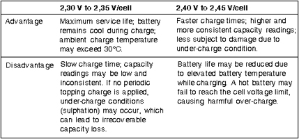
The charge voltage limit indicated in Table 1 represents a temporary voltage peak when applying a full charge cycle. The battery cannot dwell on that level. Once fully charged and at operational readiness, the float charge maintains the voltage at a lower level. The recommended float charge voltage of most low-pressure lead-acid batteries is between 2,25 to 2,30 V/cell.
The optimal float charge voltage shifts with temperature. A higher temperature demands slightly lower voltages and a lower temperature demands higher voltages. Chargers that are exposed to large temperature fluctuations are equipped with temperature sensors to optimise the float voltage.
Whereas the voltage settings in Table 1 apply to low-pressure SLA with a pressure relief valve setting of about 34 kPa, the cylindrical SLA by Hawker requires higher voltage settings. The voltage limits should be set according to the manufacturer's specifications. Failing to apply the recommended settings causes a gradual decrease in capacity due to sulphation. Typically, the Hawker cell has a pressure relief setting of 345 kPa. This allows some recombination of the gases during charge.
The price of the Hawker cell is slightly higher than that of the plastic equivalent, but lower than the NiCd. Also known as the 'Cyclone', this cell is wound similar to a cylindrical NiCd. This construction improves the cell's stability and provides higher discharge currents when compared to the flat plate SLA. Because of its relatively low self-discharge, Hawker cells are suited for defibrillators used on standby mode.
An SLA must be stored in a charged state. A topping charge should be applied every six months to avoid the voltage from dropping below 2,10 V/cell. The topping charge requirements may differ with cell manufacturers.
An approximate charge-level indication can be obtained by measuring the open cell voltage while in storage. A voltage of 2,11 V, if measured at room temperature, reveals that the cell has a charge of 50% and higher. If the voltage is at or above this threshold, the battery is in good condition and only needs a full charge cycle prior to use. If the voltage drops below 2,10 V, several discharge/charge cycles may be required to bring the battery to full performance. When measuring the terminal voltages, the storage temperature should be observed. A cool battery raises the voltage slightly and a warm one lowers it.
Some buyers who inspect the battery during quality control reject SLA batteries arriving from vendors with less than 2,10 V per cell. Low voltage suggests that the battery may have a soft short, a defect that cannot be corrected with cycling. Although cycling may increase the capacity of these batteries, the extra cycles compromise the service life of the battery. Furthermore, the time and equipment required to make the battery fully functional adds to operational costs.
How to restore and prolong sealed lead-acid batteries
The SLA is designed with a low over-voltage potential to prohibit the battery from reaching its gas-generating potential during charge. Excess charging would cause gassing and water depletion. Consequently, the SLA can never be charged to its full potential.
Finding the ideal charge voltage limit for a sealed lead-acid system is critical. Any voltage level is a compromise. A high voltage limit produces good battery performance, but shortens the service life due to grid corrosion on the positive plate. The corrosion is permanent and cannot be reversed. A low voltage preserves the electrolyte and allows charging under a wide temperature range, but is subject to sulphation on the negative plate.
Once the SLA battery has lost capacity due to sulphation, regaining its performance is often difficult and time-consuming. Reasonably good results in regaining lost capacity are achieved by applying a charge on top of a charge. This is done by fully charging an SLA battery, then removing it for a 24 to 48 hour rest period and applying a charge again. This is repeated several times, and then the capacity of the battery is checked with a full discharge. The SLA is able to accept some overcharge, however, too long an overcharge could harm the battery due to corrosion and loss of electrolyte.
Applying an over-voltage charge of up to 2,50 V/cell for one to two hours can reverse the effect of sulphation of the plastic SLA. During that time, the battery must be kept cool and careful observation is necessary. Extreme caution is required not to raise the cell pressure to venting point. Cell venting causes the membrane on some SLAs to rupture permanently. Not only do the escaping gases deplete the electrolyte, they are also highly flammable!
The Hawker cell can be stored at voltages as low as 1,81 V. Reactivation is relatively easy. However, when activating, the cell voltage under charge may initially raise up to 5 V while absorbing only a small amount of current. Within about two hours, the small charging current converts the large sulphate crystals back into active material. The internal cell resistance decreases and the charge voltage eventually returns to normal. At a voltage between 2,10 V and 2,40 V, the cell is able to accept a normal charge.
To prevent damage, current limiting must be applied to protect the battery. Always set the current limit to the lowest practical setting. If current limiting is not available, the battery should be observed at all times. Not all Hawker cells allow restoration after prolonged low voltage storage.
Improving the capacity of an older SLA by cycling is mostly unsuccessful. Such a battery may simply be worn out. Cycling would just wear down the battery further. Unlike nickel-based batteries, the lead-acid battery is not affected by memory.
SLA batteries are commonly rated at a 20-hour discharge. Even at such a slow rate, a capacity of 100% is difficult to obtain. For practical reasons, most battery analysers use a 5-hour discharge when servicing SLA batteries. This typically produces 80% to 90% of the rated capacity. SLA batteries are normally overrated and manufacturers are aware of this.
Summary
The SLA serves a market in which newer battery chemistries would either be too expensive and the upkeep too demanding. A modern replacement may simply be too delicate and fail prematurely due to harsh environment. For applications such as wheelchairs, scooters and small UPS units, the SLA has not found a suitable replacement that is both rugged and cost effective. But like any other battery, the SLA exhibits weaknesses and has needs that must be met to obtain a long and reliable service. They are:
* Always keep the SLA charged. Never store below 2,10 V/cell.
* Avoid repeated deep discharges. Charge more often.
* If repeated deep discharges cannot be avoided, use a larger battery to ease the strain.
* Prevent sulphation and grid corrosion by choosing the correct charge and float voltages.
| Tel: | +27 11 466 1156 |
| Email: | [email protected] |
| www: | www.uniross.co.za |
| Articles: | More information and articles about Uniross Batteries |


© Technews Publishing (Pty) Ltd | All Rights Reserved
 printer friendly version