


The purpose of this document is to compare Samtec’s edge rate contact to a standard stamped/cut style contact both mechanically and electrically.
Some of the attributes that will be compared include durability, normal force, insertion/withdrawal force, contact wear and signal integrity performance.
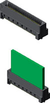
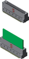
For this comparison, Samtec's HSEC8 series and MEC8 series connectors were chosen. Both of these connectors are used in edge card applications, see Figures 1 and 2. These two products were chosen because they are virtually the same connector, but with different style contact systems. Both connectors feature two rows of contacts on 0,8 mm pitch, but the HSEC8 series uses the edge rate contact system whereas the MEC8 series uses a stamped/cut contact system.
Each of these contact styles has its advantages and disadvantages depending on the application/end use. The major advantage the stamped/cut contact system has over the edge rate contact system is the ability to produce ultra fine pitch connectors. Ultra fine pitch connectors are those connectors under 0,8 mm pitch from contact to contact. Currently, the tightest pitch available on a connector using the edge rate contact system is 0,8 mm, while connectors using the stamped/cut contact system are available on 0,635 mm and 0,5 mm pitch.
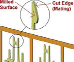
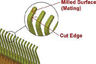
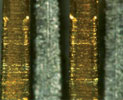
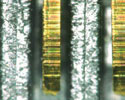
Stamped/cut contacts mate on the cut edge of the stamping which can be seen in Figure 3. This edge is considerably rough compared to the flat surface of the edge rate contact shown in Figure 4 where the contacts mate on the mill supplied surface of the contacts.
As a result of the contact fabrication, the edge rate contact will always feature a smoother mating surface. See Figures 5 and 6 for a visual comparison of the contact surfaces as seen under high resolution. This difference in contact surface finish is what contributes to the durability and wear characteristic - differences that are seen between the edge rate and stamped/cut contact systems.
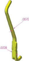
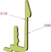
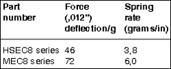
Because the stamped/cut contact is considerably thicker than it is wide, its spring rate is generally higher as compared to an edge rate contact of similar size, see Figures 7 and 8. The spring rate is the amount of normal force required to deflect the contact beam a defined unit of distance. In comparison, edge rate contacts are wider than they are thick, and thus have a lower spring rate, see Table 1. Spring rate, along with a few other variables, affects the insertion/withdrawal characteristics that a connector system exhibits. This is sometimes referred to as mating/unmating forces.
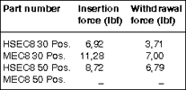
In general, the lower the spring rate, the lower the insertion/withdrawal forces. When comparing the insertion/withdrawal numbers for both contact systems, the trend is that the higher the spring rate, the greater the insertion/withdrawal force displayed, see Table 2 for examples.
The rough surface on the stamped/cut style contact will create 'wear tracks' on the contact beams. The rate at which these wear tracks are created define the durability of the connector which is more commonly referred to as cycle life. The smooth mating surface of the edge fate style contact has a slower rate of wear track growth. This allows the edge rate contact system to be rated at a much higher cycle life.
When comparing the differences between these two contacts from a high speed electrical standpoint, some general conclusions can be made. Due to the contact design/construction method, the stamped/cut style contact exhibits more coupling which in turn means more crosstalk. There are also more geometry changes in the stamped/cut style contact which can negatively affect the impedance and the return loss. For the most well behaved impedance profile, the contact that exhibits the straightest, most consistent material cross section usually performs the best.
In summary, the edge rate contact was compared to the stamped/cut style contact with regards to durability, normal force, insertion/withdrawal force, contact wear and signal integrity performance. Both contact styles have applications that they are best suited for, and even though the cost of these contact styles was not covered, this can also be a factor when determining the best overall solution for your application.


© Technews Publishing (Pty) Ltd | All Rights Reserved
 printer friendly version