


The recent boom in the deployment of optical broadband networks such as BPON (broadband passive optical networks) and GPON (gigabit passive optical networks) has generated the need for large quantities of specific optical components. These components are expected to be inexpensive, without compromising on quality and performance. Nonetheless, there are different price ranges for components and their cost may sometimes depend largely on the testing that is carried out on them during the manufacturing stage. To remain competitive, component vendors need to find efficient and cost-effective ways to test and qualify key parameters like insertion loss (IL), reflectance and polarisation-dependent loss (PDL). For components with large fibre counts - 1XN splitters, for example - optical return loss (ORL) testing can be a major source of inefficiency as some techniques necessitate a lot of handling. This application note reviews and compares two reflectance measurement methods: the traditional optical continuous-wave reflectometry (OCWR) technique and a new mandrel-free technique.
Optical continuous-wave reflectometry
The OCWR technique is achieved by sending a continuous-wave (CW) optical signal to a device under test (DUT) and measuring the total CW reflected power using a power meter in the return path. Figure 1 shows the block diagram of an OCWR measurement setup.
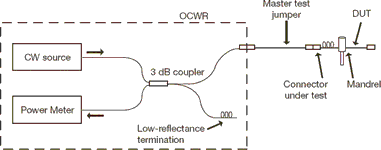
The measurement sequence implies two steps. The first step is to perform a nulling reference in order to determine the background power level that reaches the power meter, as the power is affected by the following factors:
* Directivity of the 3 dB coupler inside of the OCWR.
* Reflectance of the OCWR output port.
* Backscattering in the master test jumper (MTJ).
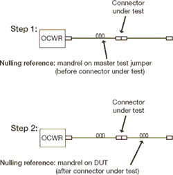
Once the nulling has been performed, the DUT can be tested. Keep in mind, however, that when using the OCWR measurement method a mandrel-wrap is required for both of these steps to ensure proper results (see Figure 2). This technique therefore implies human intervention, as a mandrel-wrap normally consists of wrapping the fibre (the one after the DUT) around a small diameter tool about 10 times.
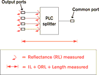
When characterising components with large fibre counts, like 1XN planar light-wave circuit (PLC) splitters, these manipulations become very time consuming. For example, in order to test a 1X32 splitter from its common port, 32 mandrels must be applied simultaneously (one for each output port of the splitter - see Figure 3).
**dw2489c.png**>
Most of the splitters, however, are pigtailed with ribbon fibre; an alternative would be to apply a mandrel-wrap at that level. However, ribbon fibre tends to be rigid and fragile, so mandrel-wrapping on those is a risky operation that is not recommended for all types of coating/buffers.
Although the OCWR technique is a simple method that works well when testing patchcords, it is not really practical when dealing with dense splitters such as those used in FTTx systems, where the number of ports may be as high as 32 or even 64.
Moreover, the OCWR technique does not measure discrete reflectance directly; it measures the ORL, which consists of discrete reflectance plus fibre backscattering.
To measure the contribution of a particular reflective event, mandrel-wraps need to be applied right before and right after the event, which is not practical when dealing with ribbon fibre or rigid cable. This restriction limits the ability to measure high performance components such as those required in FTTx networks. For example, a splitter pigtailed with 3 m of fibre would have an initial return-loss noise floor of 65 dB at 1310 nm, thus limiting the ability to qualify its connectors and/or splitter ports that typically require reflectance values better than -65 dB.
Mandrel-free reflectance measurements
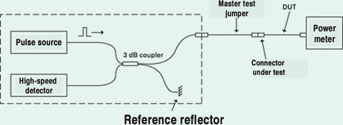
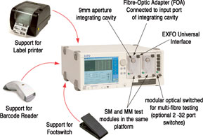
EXFO has developed a mandrel-free reflectance measurement technique to characterise cable assembly IL and reflectance. This approach, which is based on optical time-domain reflectometry (OTDR), allows for precise and repeatable measurement of reflectance and IL in one efficient step (see Figure 4). This turnkey system, the IQS-12001B, is now widely used in high-volume production by many leading cable assembly manufacturers worldwide.
EXFO's mandrel-free system has now been specially enhanced to support testing of components such as 1XN PLC splitters. The mandrel-free OTDR-based technology greatly simplifies high-fibre-count component testing. The ability of the IQS-12001B to distinguish the different reflective peaks from connectors and splitters allows users to characterise DUTs with a simple and automated test sequence. The mandrel-free reflectance measurement dramatically reduces the total measurement time as no manual operations like mandrels are required (see Figure 5).
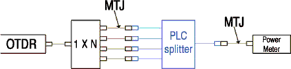
The IQS-12001B performs reflectance measurement down to -75 dB with very good accuracy and repeatability. The characterisation of a PLC splitter can be performed in a single step for each direction tested with the IQS-12001B. In a configuration such as the one shown in Figure 5, a simple sequence allows the user to characterise the input connectors and the splitter reflectance individually as well as measure IL (see Figure 6).
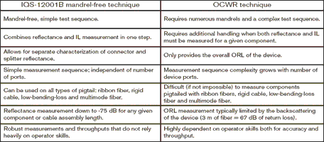
The same measurement using the OCWR technique requires three steps per direction and multiple mandrel-wrap operations (1+N mandrels). Table 1 summarises the benefits of the mandrel-free measurement over the OCWR method.
Conclusion
FTTx deployment has set new heights in terms of optical component performance and volume requirements. Telecom operators now need high-quality optical assemblies that are qualified for return loss beyond 65 dB, all in high volumes and at an affordable price, as these issues directly affect their suppliers. These suppliers, in turn, are looking for efficient and cost-effective ways to test and qualify their products to sustain these requirements.
EXFO's OTDR-based technique, not only allows users to measure discrete reflectance events down to -75 dB, but also automates the testing procedure. This approach, implemented in the IQS-12001B turnkey system, is particularly crucial for high-fibre-count components such as those required in the broadband system market.
| Tel: | +27 12 349 1341 |
| Email: | [email protected], [email protected] |
| www: | www.lambdatest.co.za |
| Articles: | More information and articles about Lambda Test |


© Technews Publishing (Pty) Ltd | All Rights Reserved
 printer friendly version