


Passive or active probe?
For general-purpose mid-to-low-frequency (less than 600 MHz) measurements, passive high-impedance resistor divider probes are good choices. These rugged and inexpensive tools offer wide dynamic range (greater than 300 V) and high input resistance to match a scope's input impedance.
However, they impose heavier capacitive loading and offer lower bandwidths than low-impedance (z0) passive probes or active probes. All in all, high-impedance passive probes are a great choice for general-purpose debugging and troubleshooting on most analog or digital circuits.
For high-frequency applications (greater than 600 MHz) that demand precision across a broad frequency range, active probes are the way to go. They cost more than passive probes and their input voltage is limited, but because of their significantly lower capacitive loading, they provide more accurate insight into fast signals.
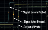
Figure 1 shows screenshots from a 1 GHz scope measuring a signal that has a 1 ns rise time. Above, a 600 MHz passive probe was used to measure this signal. Below, a 1,5 GHz single-ended active probe was used to measure the same signal. The blue trace shows the signal before it was probed and is the same in both cases. The yellow trace shows the signal after it was probed, which is the same as the input to the probe. The green trace shows the measured signal, or the output of the probe.
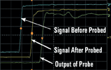
A passive probe loads the signal down with its input inductance and capacitance (yellow trace). It is often expected that the oscilloscope probe will not affect the signals in the device under test (DUT). However, in this case the passive probe does have an effect on the DUT. The probed signal's rise time becomes 1,9 ns instead of the expected 1 ns, partly due to the probe's input impedance, but also due to its limited 600 MHz bandwidth in measuring a 350 MHz signal (0,35/1 ns = 350 MHz).
The inductive and capacitive effects of the passive probe also cause overshoot and ripping effects in the probe output (green trace). The 1,85 ns rise time of the measured signal with the passive probe is actually faster than the probe's input, due to these capacitive and inductive effects.
Some designers are not concerned about this amount of measurement error. For others, this amount of measurement error is unacceptable.
It is apparent that the signal is virtually unaffected when a 1,5 GHz active probe is attached to the DUT. The signal's characteristics after being probed (yellow trace) are nearly identical to its un-probed characteristics (blue trace). In addition, the rise time of the signal is unaffected by the probe, being maintained at 1 ns. Also, the active probe's output (green trace) matches the probed signal (yellow trace) and measures the expected 1 ns rise time. Using the active probe's 1,5 GHz bandwidth makes this possible.
Check the probe coupling
With the probe connected to a signal, the user should move the probe cable around and grab it with their hands. If the waveform on the screen varies significantly, energy is being coupled onto the probe shield, causing this variation. Using a ferrite core on the probe cable may help improve probing accuracy by reducing the common mode noise currents on the cable shield.
A ferrite core on the probe cable generates a series impedance in parallel with a resistor in the conductor. This addition to the probe cable rarely affects the signal because the signal passes through the core on the centre conductor and returns through the core on the shield, resulting in no net signal current flowing through the core.
The position of the ferrite core on the cable is important. For convenience, the user may be tempted to place the core at the scope end. This would make the probe head lighter and easier to handle. However, the core's effectiveness would be reduced substantially by locating the core at the probe interface end of the cable.
Reducing the length of the ground lead on a single-ended probe will help some.
Switching to a differential probe will typically help the most. Many users don't understand that the probe cable environment can cause variations in their measurements, especially at higher frequencies, and this can lead to frustration with the repeatability and quality of measurements.
| Tel: | +27 12 678 9200 |
| Email: | [email protected] |
| www: | www.concilium.co.za |
| Articles: | More information and articles about Concilium Technologies |


© Technews Publishing (Pty) Ltd | All Rights Reserved
 printer friendly version