


As operating frequencies of equipment continue to increase, dynamic loads become increasingly important. Transient response – the ability of the power converter to respond to a change in the load requirement – has become increasingly important as clock rates have increased with each succeeding silicon process generation.
Processors and high density digital ASICs, for example, have load requirements that can dramatically change as the device shifts from power-saving or idle states to fully clocked, creating near instantaneous load transients - up to 50 or 100 A/μs or more in current generation microprocessors. If a converter is unable to respond to this transient load step, the output voltage of the converter drops. That can cause system havoc, as the unit drops below its required operating voltage and shuts down, potentially requiring the system to reboot.
Methods of optimising the transient response are available to the power designer, but no one method suits all applications; each application is unique. Maximising transient response requires customising a power solution for the specific load type. Once the transient response requirements of a load are properly characterised, many options and trade-offs can be addressed to optimise the converter's dynamic response.
The power system designer can consider a number of methods, such as point-of-load capacitance, active transient attenuation, point-of-load conversion, or single-filter point-of-load capacitance. Additional considerations include power converter design, output filter design, and proper layout to minimise trace inductance and trace resistance.
Point-of-load capacitance
The typical converter is much slower than a microprocessor. Designers typically deal with this deficiency by storing a large reservoir of energy in capacitors at the output of the converter close to the load, ie, at the point of load. The amount of capacitance needed to provide a current without very much voltage for enough time for the converter to get up to speed, is substantial, often many thousands of microFarads.
Nevertheless, POL capacitance is easy to adapt to a standard converter (see Figure 1) for a specific application. Different capacitors can be used to adapt the same converter to a variety of loads.
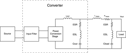
The disadvantages are a complex output filter formed by the load capacitance and parasitics, which may make it difficult for the control loop to provide compensation. Also, the shape and magnitude of the transient response is modified. Typically, the peak deviation is decreased but the settling time increases. It also does not solve transient-related issues of the ESR and ESL of the capacitor, usually necessitating more than one capacitor and capacitor type with associated costs and reliability concerns.
Finally, point-of-load capacitance can potentially be a problem because a capacitor takes up space on a board - which is precious these days - and it is a failure-prone device that costs money.
Active transient attenuation
To introduce active transient attenuation (see Figure 2), the designer can add an active device between the converter's output and the load. This method has the advantages of combining a low pass filter and an active series pass element to provide transient attenuation. Since attenuation involves a low-pass filter, there is an element of energy storage somewhat mitigating the effects of parasitics. It also allows the standardisation of the power converter.
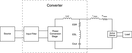
Active transient attenuation, however, reduces the system efficiency, it does not totally eliminate all the transient response issues, and it adds components and complexity to the system.
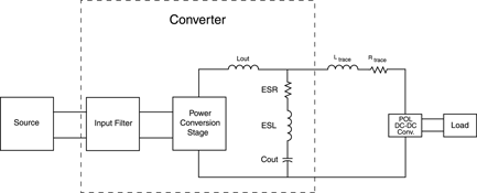
Point-of-load conversion
For point-of-load conversion, an additional DC-DC converter is added between the output of the upstream converter and the load. This method provides close coupling between the converter and load to mitigate the effects of parasitics. The point-of-load converter can be small and provide high efficiency, but it still reduces system efficiency.
Further disadvantages include the facts that it reduces system efficiency, it has its own control loop and transient response issues, and it adds additional cost, components and complexity to the system.
Single-filter point-of-load capacitance
Another approach, which introduces a unique converter, is a single-filter point-of-load capacitance converter. The advantages are that the parasitic inductance and resistance are not only mitigated, but consolidated and effectively appear as part of the output inductance.
The converter can be located remotely from the load, freeing up real estate around the load. This can be a highly cost-effective solution since the output filter is at the load only and does not exist within the converter itself; therefore, the part count is kept to an absolute minimum.
This approach, however, does require a unique converter design, and it still does not eliminate the transient effects due to the ESR and ESL of the output capacitor(s).
Additional considerations
An additional factor to consider is the choice of the output capacitor.
Ceramic capacitors have low ESR (equivalent series resistance) and low ESL (equivalent series inductance). However, they have low capacitance per unit volume. They are low-cost and some may lose capacitance as high voltages are applied.
Electrolytic capacitors have high ESR, and typically the interconnect used within a device creates high equivalent series inductance. They do have high capacitance per unit volume and they have moderate reliability. The designer must make sure that the current through the device does not exceed the specifications.
Film capacitors have low ESR and very low ESL. They have high voltage tolerance and low capacitance per unit volume.
Tantalum capacitors have very low ESR, very low ESL, and very high capacitance per unit volume. They do have low voltage tolerance and low reliability. The designer must ensure that the RMS currents are within specifications as catastrophic failure could occur.
In the application, it is important to exercise good design practice. Minimise trace resistance and inductance.
For trace resistance, use only high-grade copper in wide traces for the plus and minus output to the load. Try to minimise the distance between the converter and the load and minimise the number of connectors used between the converter and the load.
For trace inductance, keep the current loop path from the +OUT to the -OUT as small as possible. Use twisted pairs if wires are used for interconnecting the converter's output to load. Run the positive or negative traces in separate planes on top of each other if the PC board traces are used in connecting the converter's output to the load. Run the traces and/or the wires such that they are routed away from magnetic fields and components.
Finally, for applications with high di/dt loads, it is important to choose the power converter carefully. These are some of the things to consider when evaluating the converter:
* Is the stated performance acceptable for the application?
* Do the stated test conditions of the converter match or exceed the load requirements?
* Is the converter capable of handling the dynamic load requirements?
* What additional components are necessary to meet the transient requirements?
* What size is the converter?
* Where will the converter need to be mounted with respect to the load?
* What parasitics will be introduced by mounting the converter in a certain location?
* What are the trade-offs between real estate and parasitics?
* How will these parasitics affect the converter's performance?
* How will these parasitics affect the transient response?


© Technews Publishing (Pty) Ltd | All Rights Reserved
 printer friendly version