


In modern electronics systems, where the ambient temperature lies above 55°C or a high performance per area or volume is demanded, water cooling is often the only solution. Water has a specific heat capacity which is higher by a factor of 4000 than air (relating to volume) and is thereby considerably more suitable for the cooling of critical components.
A further advantage of pure water cooling is the omission of fans, which, as the noisiest parts of the entire system, are no longer required. Possible noise pollution problems can therefore also be solved. Furthermore the transportation of the cooling fluid to a suitable location, where the heat is extracted and can possibly be used subsequently, can be realised in a relatively simple manner
Standard for water cooling
As early as 2006, the IEC Committee SC 48 D dealt with the subject of water cooling and a new standard for the cooling of electronics cabinets was developed. The aim of this standard is the provision of guidelines for the selection of air/water heat exchangers with performances of up to 35 kW for cabinets and subracks and the statement of parameters which result from different configurations.
Furthermore, basic requirements for the water cooling on board level are defined. With this the user should receive a practical planning and configuration aide. The IEC/TS 62454 Ed.1.0 divides water cooling into three levels.
* Level I - Cabinet platform: Cabinet with an air/water heat exchanger (base or side assembly). A global viewpoint, whereby the entire control cabinet/electronic enclosure is cooled with an air/water heat exchanger.
* Level II - Shelf (subrack) platform: Cabinet with a smaller air/heat exchanger, which is located at the side, to cool an individual subrack or a group of subracks.
* Level III - Board platform: The lowest platform, where the water cooling has a direct impact on the boards or chips.
With Level III the possible cooling solutions are so numerous on account of the different dimensions and positions of the components which require cooling, that the members of the standard consortium decided not to restrict this by too strict definitions. Therefore, Level III only defines that water connections have to be present in the cabinet, which lead to quick connectors at the front and rear of the plug-in units. Only the principle of the water cooling of the individual components is outlined. The detailed configuration is left to the manufacturers/users.
Water cooling at cabinet or subrack level
Looking at the solutions offered on the market on the subject of water cooling, one finds those which remove heat at cabinet or subrack level (Levels I and II). These are usually hybrid solutions. This means that the electronics in the subrack are air cooled as before.
The heated air is cooled via an air/water heat exchanger and then returned to the cabinet. In this way a closed cooling circuit is created, which has advantages and disadvantages. The advantage lies in the larger DT (temperature difference), which results from the re-cooling of the air to a level below the ambient temperature. Following the general formula for the required air stream for the cooling (V = k x PV /ΔT), the required air volume automatically becomes smaller through a larger DT.
During the cooling of ambient temperature, as a rule, one achieves a ΔT of 10 to 15 Kelvin; with re-cooling via a heat exchanger DT lies around 30 to 35 Kelvin. With the same cooling result, the required air volume is smaller by two thirds. The big disadvantage with this solution is the generation of condensed water, when the closed circuit is interrupted by not being airtight or repeated opening of the enclosure. Here measures to collect/dispense the condensed water have to be considered.
A pure fluid cooling on these levels in an electronics cabinet, that is without the assistance of a fan in the internal air circuit, cannot easily be planned, as the performance yield would be relatively meagre. Despite this there are some water-cooled assembly plates offered on the market, to enable the direct assembly of direct electronic components.
Water cooling at board level
In Level III of the IEC/TS 62454 Ed.1.0 a solution is outlined, where heat is dissipated by pure water cooling directly where it is generated, which is on the components of the plug-in units inside the subrack. In particular the new high performance processors generate heat, which, in relation to area, exceeds by far that of a hot plate. Assuming a 200 W board with two processors, these two processors generate approximately two thirds of the heat. Schroff has therefore developed special frame-type plug-in units (Figure 1) which can be integrated into conventional subracks and in which the boards with particularly critical components are cooled with water via a so-called cold plate.
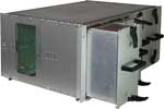
These cold plates consist for instance of recessed aluminium plates, into which the copper or stainless steel pipes are press-fitted. Thus normal tap water can be used for the cooling. Coordinated with the required performance loss and the geometric requirements, each cold plate is arranged specifically to user requirements. The flow rate through the pipes can range from 2 to 16 l/min. The electronic components can be assembled on both sides of the cold plate.
Drip-free fast couplings
The supply and return of water is realised via a coupling plate, which is located at the rear of the subrack. When the unit is inserted into the subrack (Figure 2) the electrical contacts are made as usual
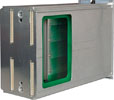
At the same time the connection to the coupling plate takes place via drip-free fast couplings. These are floating so that possible tolerances in X and Y directions can be compensated for (Figure 3).
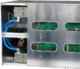
Despite their small dimensions, these fast couplings guarantee high flow rates in both directions and are arranged for approximately 1 million tact cycles and a maximum operating pressure of 450 bar. Depending on the temperature field, different sealing materials can be used: Nitril (NBR, -15 to +100°C), Fluor Carbon (FPM, -10 to +150°C) or Ethylene-Propylene (EPDM, -20 to +150°C).
The following calculation example illustrates the cooling capacity of a cold plate:
With a water volume of 10 l/min, components requiring cooling assembled on both sides, a water pre-run temperature of 18°C and a maximum surface temperature of the cold plate of 35°C, the maximum cooling capacity of the cold plate is calculated as:
How much of the maximum cooling capacity can be used basically on three factors:
* The quality of the contact between the component requiring cooling and the cold plate.
* The heat conductivity of the heat conducting paste or heat conducting foil.
* The size of the contact surface between component and cold plate (as a rule only a small part of the possible total cooling surface).
The big advantage of fluid cooling, ie, being independent from the ambient temperature of the installation site, can be employed optimally with pure water cooling at board level. Whilst with air cooling it always has to be observed that the cooling air has a lower temperature than the component in need of cooling, fluid cooling operates independently of the room temperature. Due to the possible formation of condensation, it should preferably be around 16°C or above. Furthermore, fluid cooling is clearly less noisy than air cooling or a hybrid solution and is far more maintenance friendly.
| Tel: | +27 11 608 3001 |
| Fax: | +27 11 608 1918 |
| Email: | [email protected] |
| www: | www.actum.co.za |
| Articles: | More information and articles about Actum Electronics |


© Technews Publishing (Pty) Ltd | All Rights Reserved
 printer friendly version