


Power supplies, forming an integral part of almost every electronic system, are now a significant market in their own right, and one which is growing at a tremendous rate.
For many years, power supply designs have consisted of complex combinations of analog and power semiconductor components, with that complexity increasing more recently as the proportion of switched-mode power supplies (SMPS) grows, taking over from traditional linear designs. In fact, by current estimates, more than half of the revenue for power supply producers worldwide is now generated by the sale of switched-mode supplies.
A switched-mode supply can offer many advantages over a linear supply, such as dramatically increased efficiency, wider operating ranges, lower cost and smaller size, particularly for higher wattage applications. However, the many advantages of a switched-mode supply have now become the normal expectations of power supply performance, and designers are increasingly looking to digital control loop implementations to offer even greater efficiency and performance, as well as reducing component count, increasing manufacturability and reliability, and allowing the addition of advanced features.
What is a switched-mode power supply?
An SMPS can be used for both AC to DC conversion and also for DC to DC conversion applications such as uninterruptible power supplies (UPS).
The traditional, linear design for AC to DC converters uses a large (and heavy) transformer to step down the incoming AC. This lower voltage is then converted to DC, typically using diode rectification (with its inherent losses). The rectified voltage is then filtered using large filter capacitors and inductors as required.
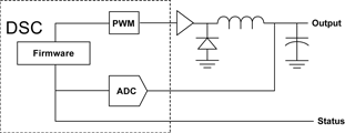
A switching AC to DC supply converts the incoming AC to lightly-filtered DC and then ‘chops’ this DC voltage at high frequencies. The pulse width of the ‘chopped’ DC signal is controlled by feedback from the output, to regulate the overall output voltage of the supply. This control method is therefore known as pulse width modulation (PWM). The high frequency chopped signal is then applied to a smaller transformer to step down the voltage. The transformer can be much smaller due to the high frequency of the chopped DC signal. This low voltage, high frequency output of the transformer is then rectified. The rectification is sometimes achieved using synchronised FETs rather than diodes to minimise losses. In addition, because the ripple frequency is high, much smaller filter capacitors and inductors can be used.
Switched-mode power supply control methods
Within a switched-mode supply, the control loop that drives the PWM (the ‘chopper’) and the synchronous FETs is typically accomplished using analog techniques. It has long been possible to replace these analog techniques with some form of digital control, but until recently, the techniques and components have been too expensive for all but the most specialised applications.
As a result, most expert SMPS designers remain unfamiliar with digital control techniques, since they have been developing increasingly divergent and esoteric analog circuits to try and remain cost-effective while achieving a competitive edge in their own particular market.
Microcontrollers in power supply designs
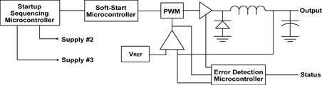
Outside of the control loop functions, simple microcontrollers have already found their way into many SMPS designs to provide control, monitoring, deterministic functions and communication (usually based on I²C – such as the emerging PMBus standard for example).
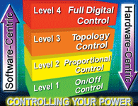
At the simplest level, microcontrollers can provide many ‘on/off’ deterministic functions within the power supply system such as soft-starting, start-up sequencing, voltage monitoring and fault detection/recovery. Some SMPS designs use a microcontroller to supervise the control loop, by providing proportional control of an existing, dedicated power supply controller device.
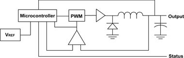
More advanced microcontrollers, specifically targeted at the power supply market, can provide mixed-signal, on-chip resources to assist in minimising the overall component count and to take a more active role in controlling the topology of the SMPS control loop. However, in all of these instances, the control loop itself remains an analog function, since microcontrollers simply do not have the processing performance to effectively manage the loop digitally.
The advantages of a digital control loop
The implementation of a switched-mode power supply using a fully-digital control loop can, however, bring many advantages over analog-based designs.
The ability to rapidly support differing customer requirements (such as capacitive or inductive loads) can be provided by simple software customisation of the supply’s response characteristics. Software configurability can give the ability to support different supply topologies with a common hardware platform, or even modify the system topology on the fly, based on an input voltage such as a decreasing battery supply. Systems can also be supported with firmware upgrades in the field.
Using a common hardware platform with software customisation can also provide many manufacturing and sourcing advantages. Manufacturability of a digitally controlled design is also increased by the reduced overall component count, the ability to automatically compensate for component tolerances, the elimination of component tolerance in the loop filter, and the greatly simplified end of line testing that is possible. The reduced component count is also an advantage in small form-factor power supply designs.
Although not exclusive to fully-digital designs, the ability to rapidly process multiple control loops can make it easier to add other advanced features to a power supply design such as independent control of, and load-sharing between, multiple supply rails in a single design the integration of Power Factor Correction (PFC) and even adaptive, predictive control of the PWM frequency to mitigate any control loop/communication delays, optimise transient response and improve efficiency and performance.
Other advantages, only offered by full digital control, include the ability to have response characteristics that cannot be achieved with an analog control loop, and faster acquisition and response by ‘pre-loading’ the loop filter, and supporting non-linear loop responses. In addition, automatic system calibration and compensation for temperature, input voltage and load, synchronisation of the power conversion process to external events and hot-swap capability can all be readily provided if required.
The integrated processing capability required for a fully-digital design can also accommodate other microcontroller functionality previously mentioned such as voltage monitoring and under-/over-voltage lock-out, remote sensing, soft-starting, supply sequencing, fault-handling, fan control and failure detection, and serial communication – all without requiring an additional processor.
While the overall benefits of digital control are clear, the cost associated with implementing it has traditionally restricted it to only those applications that truly require the advanced control features that it can support.
Implementing cost-effective digital control
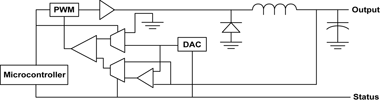
A new class of high-performance microcontroller with integrated signal processing capability – termed a digital signal controller (DSC) – is now providing the processing performance needed to implement a cost-effective, fully-digital control loop for most power supply applications.
A good example is Microchip’s dsPIC DSC – a 30 MIPS, 16-bit Flash-based microcontroller with extensive DSP capabilities that give the device the ability to, for example, process a simple proportional integral differential (PID) control loop with a control throughput of over 600 kHz. The standard dsPIC devices feature flexible clocking options, reset control and power-management features, and hardware peripherals (such as serial communications) that lend themselves to power supply applications. In addition, the devices are available in very small package options, including a 6 x 6 mm QFN package, and support extended temperature operation, up to 125°C.
In order to cost-effectively offer the highest performance possible, Microchip has further developed the dsPIC devices to offer highly optimised PWM, comparator and analog-to-digital converter modules specifically for power supply applications. When combined, these three modules can provide low latency, flexible, high-resolution control loops for both voltage and current feedback.
| Email: | [email protected] |
| www: | |
| Articles: | More information and articles about Tempe Technologies |


© Technews Publishing (Pty) Ltd | All Rights Reserved
 printer friendly version