


Today, power conversion is usually accomplished with high-density DC-DC converter components based on high-frequency switching technologies.
Efficient high-frequency operation has long been recognised as the key to achieving high power density and improved performance in switch-mode converters. High-frequency operation translates into smaller magnetic components and capacitors, faster response times, smaller filters and lower noise levels.
Notwithstanding noise performance improvements, all DC-DC converters generate electromagnetic interference (EMI) or noise. This noise – common-mode, differential mode, and radiated noise – can vary widely among DC-DC converters from supplier to supplier and topology to topology.
Although the many designs, or topologies, of DC-DC converter components certainly number in the hundreds, two are dominant: so-called fixed-frequency pulse-width modulation (PWM) and variable-frequency quasi-resonant zero-current/zero-voltage switching (ZCS/ZVS). Design engineers working with DC-DC converters must understand the noise performance differences of these two main topological classes.
Fixed-frequency PWM converters inherently trade off efficiency against operating frequency because of switching losses. Power – and noise as well – is dissipated in the switching element each time it discontinuously makes and breaks inductive current flow during its brief turn-on and turn-off transitions. Power dissipation due to switching losses increases directly with operating frequency in PWM converters until it becomes a dominant loss factor. At that point, efficiency declines rapidly, and the thermal and electrical stresses on the switch element become unmanageable. The losses result in a 'frequency barrier' that limits achievable power density in conventional converters.
Variable-frequency quasi-resonant ZCS/ZVS converters overcome the frequency barrier by implementing a forward converter switching at zero current and zero voltage. Each switch cycle delivers a quantised 'packet' of energy to the converter output, with switch turn-on and turn-off occurring at zero current and voltage, resulting in an essentially lossless switch. ZCS converters can operate at frequencies in excess of 1 MHz. By eliminating the fast current discontinuities characteristic of conventional topologies, ZCS/ZVS results in a virtually lossless transfer of energy from input to output with dramatically reduced levels of conducted and radiated noise.
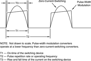
The noise generated by the switch is a major difference between PWM and ZCS/ZVS converters. Among other differences, ZCS/ZVS converters have sinusoidal waveforms rather than the square waveforms of PWM converters. The lack of sharp edges and lower harmonic content of ZCS/ZVS results in much less excitation of parasitic capacitance and inductance, resulting in less noise. With pulse-width modulation, the input voltage is switched at a constant frequency (usually several hundred kilohertz) to create a pulse train. The width of the pulses is adjusted to provide the necessary power to the load at the correct voltage. At full load, the current waveform looks much like a square wave (see Figure 1).
Many designers intuitively assume that it is easier to design a filter for a fixed frequency converter than for a variable frequency converter. In fact, the opposite is true1. The perception is, in all likelihood, attributable to the term 'fixed frequency', which is actually a misnomer. Both topologies have frequency elements that are more or less fixed and frequency elements that vary as a function of operating conditions.
Figure 1 compares the waveforms of the current flowing through the main switch. In a module using a quasi-resonant topology, the pulse width or on-time, T1, is fixed, while the repetition rate or period, T2, is variable. Conversely, in a module using PWM, the opposite is true; the repetition rate is fixed and the pulse width is variable. The rise/fall time, T3, is a fixed frequency in both topologies.
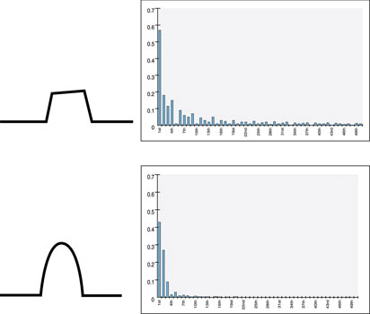
In the variable-frequency design, however, there are no high-frequency components associated with the leading and falling edges of the current waveform, T3, because it is essentially a half-wave rectified sine wave. The spectral content of the variable frequency waveform is lower in amplitude and contained in a narrower band. Characteristic harmonic spectra for each of the topologies are shown in Figure 2. In the fixed-frequency waveform, the spectral content is higher in amplitude and spread over a broader range of harmonics.
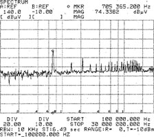
A more difficult aspect of converter EMI to control is that of parasitic excitation by high di/dt in PWM converters. This excitation results in high-frequency noise in the range of 10–30 MHz. This noise can be very difficult to suppress because it is often coupled to the secondary of the converter (through the transformer) as common-mode noise. With ZCS/ZVS converters, much less parasitic noise is generated due to the 'soft' edges of the current waveform. Figure 3 shows a typical comparison.
Clearly, for applications that require low noise, an effective first step to minimise noise generated by the DC-DC converter is to select a topology – such as zero-current switching – that is inherently lower in common-mode noise. Also, some products should be avoided in noise-sensitive applications. Control devices mounted on copper plates, for example, create parasitic capacitance from primary referenced control devices to secondary referenced control devices through the copper base, resulting in high common-mode noise. Incidentally, even in applications where no EMI requirements need to be met, bypass capacitors are typically used at the input and output pins of DC-DC converters. They are the most effective way to reduce common-mode noise.
Although component power modules usually incorporate some internal input and output filtering, additional external filtering is often needed to meet either system requirements or agency specifications. For example, FCC and European agencies specify the allowable levels of power supply noise that may be conducted back into the AC line.
Many designers tackle these issues on their own, but most DC-DC converter manufacturers provide detailed application notes and offer the assistance of a knowledgeable, experienced and easily accessible applications engineering staff. In addition, some DC-DC converter suppliers also offer AC front ends and EMI filters as modular accessories. These filters not only save time; they are a means of risk prevention as well. The EMI filter is designed to work with the supplier’s converter modules and, assuming proper layout, the combination is certified to meet the specified EMC directives.
In the US and Europe, conducted noise emissions are governed by the Class A and Class B limits of both FCC and VDE standards. In the US, the FCC requires compliance with Class A for equipment operating in factory settings and Class B – the stricter standard – for equipment destined for home use. In Europe, all countries require that equipment for both home and factory use meets the VDE Class B standard.
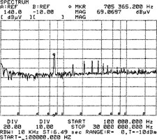
Most switching power supplies today operate in the frequency range between 100 kHz and 1 MHz. Usually, the dominant peaks in the conducted noise spectrum reflected back to the power line correspond to the fundamental switching frequency and its harmonic components. Conducted emissions standards such as EN55011 and EN55022 set quasi-peak and average limits on conducted noise reflected from the input of converters or power supply systems back to the source over the frequency range of 150 kHz to 30 MHz. In order to comply, all of the conducted noise – the peaks in the spectrum – must fall below the specified limits.
EMI filters are most often constructed in a single package, with configurations similar to that shown in Figure 4. The EMI filter is a through-hole filter with a common-mode choke and Y-capacitors (line-ground) plus two additional inductors and an X-capacitor (line-line). Transient protection is provided by Z1.This filter configuration provides sufficient attenuation to comply with the Level-B conducted emissions limit.
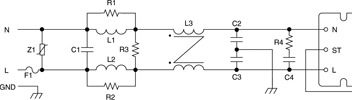
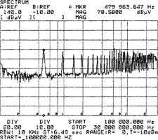
Figure 5 shows a comparison of conducted input noise generated by ZCS and PWM DC-DC converters. Notice that the unfiltered noise performance of the ZCS converter shown in Figure 3 is superior to the filtered noise performance of the PWM converter.

Reference
1. L. Hsiu, M. Goldman, R. Carlsten, A. Witulski, and W. Kerwin. 'Characterisation and comparison of noise generation for quasi-resonant and pulsewidth-modulated converters'. IEEE Transactions on Power Electronics, Vol. 9, No. 4, July 1994.


© Technews Publishing (Pty) Ltd | All Rights Reserved
 printer friendly version