


In the real world, the motor selection process can be complex and the decision must balance the ease of control with other system-related variables such as ease of maintenance, system response to failure, operating environment, thermal management and cost.
Synchronous DC motors dominate high-performance motor control because they are easy to control. This is especially true if the application requires controlled motor torque, velocity or position. As the motor torque of a DC motor is an approximately linear function of the input current, it is relatively easy to derive solid performance out of a DC motor with proportional-integral-derivative (PID) controllers.
AC induction motors (ACIM) have distinct advantages over other types of motors and are used when applications need a robust, fixed-speed solution and the evolution of microcontrollers (MCU) and power electronic devices means inexpensive variable-speed control of an ACIM is a viable option.
Whilst ACIM cannot match the performance of DC motors using basic control methods, field-oriented control (FOC) using a digital signal controller (DSC) brings DC control techniques to AC motors and simplifies the motor-selection process.
How a motor works
Let us review some motor theory basics before going further.
An electric motor produces a mechanical force when current flows in proximity to a magnetic field. A synchronous motor has a magnetic field source which can be provided by permanent magnets or by windings that are energised with a source of current. Within limits, the torque response of the motor is a linear function of the current and the magnetic field strength. The linear response makes these motors easy to control in high-performance applications. A PID controller can be used to control the motor current and the resulting motor torque. If needed, secondary PID controllers can be used to control position or velocity.
Whilst synchronous motors with field windings or permanent magnets provide good control, the motor selection process is more complex than control alone. Using a motor with rotor and stator windings can deliver high power but would mean replacing brushes and keeping the rotor cool. Using a brushless motor with permanent magnets could be an alternative, but the cost of the magnets could be prohibitive.
AC induction motors
ACIMs eliminate the disadvantages associated with synchronous motors because the ACIM has windings on the outside of the motor, which makes it easy to provide cooling. The rotor is a simple steel cage which is both durable and able to withstand high temperatures, and the ACIM has no brushes to wear out.
Since AC power is widely available, the ACIM is usually designed for a specific line voltage and frequency. As an example, the plate on the side of an ACIM could show that it is rated for the following performance parameters: voltage of 230 V a.c., frequency of 60 Hz, full load amperes (FLA) of 1,4 A, 1/3 horse-power (hp) and 3450 revolutions per minute (rpm).
The stator windings of the motor are arranged so that a rotating magnetic field is created when energised with AC currents. The rotor of an ACIM must turn at a lower speed than the rotating field. The difference between the field speed and the rotor speed is called slip. Slip can be expressed as a ratio or a frequency, but it is helpful to consider the slip frequency. For the motor in the example above, the rotating field speed would be 3600 rpm (60 rev/s) whilst the stated rpm under load is only 3450 rpm (57,5 rev/s). The slip frequency therefore is 60 Hz - 57,5 Hz = 2,5 Hz.
In this example, the 2,5 Hz slip frequency can be considered as a source of AC power that supplies energy to the rotor via transformer coupling. The rotor becomes energised with AC currents that produce a rotor magnetic field, allowing the motor to produce torque. The ACIM slip gives the motor the ability, to some extent, to self-regulate its speed. As the motor load is increased, the rotor speed will decrease. The slip frequency will then increase which, in turn, increases the rotor current and the motor torque.
Variable-speed ACIM control
An ACIM can be operated at different speeds and torque levels by varying the frequency and voltage supplied to the motor. Suppose that the example motor needed to operate at half the rated speed. To accomplish this, the frequency input to the motor would need to be reduced to one half, or 30 Hz. To operate the motor at one quarter speed, the frequency would need to be reduced to 15 Hz.
The stator field also needs to be maintained at a relatively constant level by keeping the stator current constant. The ACIM motor is inductive and the stator current will increase as the input frequency is decreased. Therefore, the input voltage needs to be reduced by a proportionate amount when the frequency is decreased. A constant V/Hz profile is often used to provide variable-speed operation of an ACIM. The V/Hz constant for the motor in the example above can be calculated by dividing the operating frequency into the operating voltage:
K = V/Hz = 230/60 = 3,83
Therefore, required drive voltage can be calculated for the required input frequency:
Voltage = K x frequency
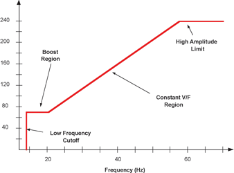
The result is called the Volts-Hertz profile and can be plotted as shown in Figure 1. There is no fixed rule that says the drive voltage has to maintain a fixed linear relationship to frequency. In fact, the shape of the V/Hz profile is often altered in specific frequency ranges to optimise the drive performance in a particular speed range. For example, the shape of the profile shown in Figure 1 has been adjusted to provide higher voltages in the low frequency range. This modification provides a boost to the motor torque when the motor starts from rest to help overcome load friction and inertia. Within the mechanical limits of the motor, the drive frequency can also be increased beyond the stated value to achieve a higher speed. However, the available voltage may be limited, so motor torque will also be lower.
For applications that do not require frequent speed or load variations, the V/Hz method of ACIM control works well. This is especially true when control loops are used to regulate speed or motor current. A typical system block diagram that can be used for a V/Hz application is shown in Figure 2.
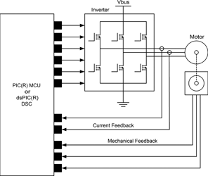
The PIC microcontroller used in this circuit has a specialised PWM peripheral to drive a 6-transistor inverter circuit. The MCU measures the frequency of the motor tachometer, calculates the speed error, and generates a drive demand using a PID control loop. The drive demand is translated into a required voltage and frequency using the V/Hz profile. Finally, the PWM modulation code varies the duty cycle over time to generate sinusoidal drive signals with the proper amplitude and frequency.
The response provided by the V/Hz control method will be too sluggish for applications that require a fast dynamic response and, furthermore, the motor currents will be very high during load or speed changes. The sluggish response occurs because the components of the stator current that control motor torque and the rotor field cannot be separated. A change in drive voltage or frequency will cause a change in both torque and rotor currents.
Ideally, the algorithm should control motor torque independently of other motor variables, and the FOC algorithm accomplishes this goal. Whilst the V/Hz method controls the speed, it does not control the phase, whereas FOC controls the voltage, frequency and instantaneous phase of the motor voltage to produce the desired stator currents. This delivers the best motor efficiency and dynamic response for a given application.
FOC – A matter of perspective
If the motor is observed electrically from the perspective of the input terminals, all signals inside the motor will appear sinusoidal. Sinusoidal signals can be difficult to process in software, especially if PID controllers are used to regulate motor currents. However, by changing the point of reference used in the calculations, the signals inside the AC motor can be made to look mathematically like DC values under steady-state conditions.
Specifically, FOC measures the AC motor currents. In a stationary reference plane, the 3-phase stator currents can be combined to form a single rotating current vector in time. Instead of using a stationary reference, a rotating reference plane that turns synchronously with the motor can be used. With the rotating reference plane, steady-state AC quantities look stationary.
A race-track provides a useful analogy: imagine standing on the side of a circular car race track. From a stationary perspective, all of the cars seem to be moving around the track at a very high speed, making it hard to see which car is winning the race because the pack of cars goes by so quickly.
Now, instead of watching the cars from the side of the track, imagine driving next to the lead car. From this perspective, the pack of cars becomes more or less stationary. The only thing that changes over time is the relative position of all the other cars to the lead position, which is the moving reference point. The actual speed of the cars moving around the track becomes irrelevant.
To apply this analogy to the motor, the speed of the cars moving around the track is comparable to the motor drive frequency. The relative position of the cars is comparable to the phase of the stator current vector.
FOC coordinate system transformations
FOC uses a pair of conversions called the Clarke and Park Transforms to get from the stationary reference plane to the rotating reference plane. First, two of the three phase currents are measured. The value of the third phase current does not need to be known or measured because the sum of the 3-phase currents should be 0. The measured currents represent the vector components of the current in a 3-axis coordinate system with each axis separated by 120°.
It is easier to represent the rotating current vector in a 2-axis orthogonal coordinate system, so the Clarke Transform just converts the measured currents so that the current vector is represented with two vector components instead of three. The two vector components calculated using the Clarke Transform still vary with time.
Clarke Transform equations:
Iα = Ia
Iβ = 0,577(Ia +2Ib)
Next, the Park Transform is used to rotate the 2-axis coordinate system so that is aligned with the rotating motor:
Park Transform equations:
Id = Iα*cosθ + Iβ*sinθ
Iq = -Iα*cosθ + Iβ*sinθ
where the rotation angle is represented by θ.
When using FOC for a synchronous 3-phase motor, the rotating reference plane would always be aligned with the rotor and could be obtained directly from the rotor position using a sensor. However, an ACIM is an asynchronous machine that requires slip to operate.
One method that can be used to calculate is to use equations that model the rotor currents. The rotor-current model calculates the required slip frequency from the measured stator currents. The rotor-current model also requires knowledge of the rotor resistance and inductance. These values form a time constant that adjusts the motor slip to the correct value during transient current events. After a slip frequency has been calculated, a value of θ can be calculated using the rotor velocity, which will align the reference plane ahead of the rotor to provide the slip. So, the rotating reference plane is aligned with the applied stator current vector, which spins faster than the rotor.
DC current?
The key to FOC is that the Clarke and Park transformations provide DC representations of the stator phase currents under steady state conditions. But, the motor current is really an AC signal represented as a rotating current vector and it is only because the coordinate system is synchronously rotating with the current vector that the transformed current components appear as DC values. If the value of either current component changes over time, this means that the amplitude and phase of the motor current vector has changed.
Most importantly, one component of the transformed stator current vector determines the amount of motor torque. The other component determines the rotor field. With FOC, the component of current responsible for motor torque can be isolated and controlled separately. This is why FOC enables an AC motor to be controlled like a DC motor.
Figure 3 shows a time history of the transformed torque current component, taken from an actual FOC application during a 2x speed increase. This is the signal that the FOC algorithm sees, instead of the AC current signal that was measured at the motor terminals. This signal represents the current required to accelerate the motor to the new speed.

The FOC control loops
In practice, the two transformed current components are separately regulated using PID controllers in software. The outputs of the two PID controllers provide two voltage vector components that determine how the motor phases need to be energised to produce the desired stator currents. The reference input for one PID controller is set to a constant value so that the rotor will generate a constant field. The reference input to the other PID controller determines the amount of motor torque. The reference torque level is usually supplied from a third PID control loop that regulates the motor speed.
The last step in the FOC process is to unwind the voltage vector components that were generated in the rotating reference plane. The value of that was calculated in the rotor current model equations is used, along with inverse Clarke and Park Transforms which are very similar to the forward transforms shown above.
FOC summary
FOC controls the amplitude, frequency and phase of the voltage vector to produce the desired amplitude, frequency and phase of the motor currents, and offers the best efficiency and dynamic response from an ACIM.
The equations for FOC are not complex, but they must be executed relatively frequently to get good performance. Using the old value of θfrom the prior iteration of the FOC equations, the measured current values are transformed and the new value of θ is calculated using the rotor current model equations. These FOC equations are typically executed every 50 μseconds to minimise the amount of angular error between iterations and therefore need a fast 16-bit MCU or DSC, such as Microchip’s dsPIC30F and dsPIC33F DSC families.
| Email: | [email protected] |
| www: | |
| Articles: | More information and articles about Tempe Technologies |


© Technews Publishing (Pty) Ltd | All Rights Reserved
 printer friendly version