


In recent years, engineers working on mobile phones and other battery-powered devices have demanded higher-sensitivity current measurement to help them ensure that the current consumption of their devices is within acceptable limits.
Measuring current is a nuisance because it is necessary to break the circuit to put the measuring instrument in series with the circuit.
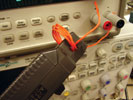
Using a clamp-on current probe with an oscilloscope is an easy way to make current measurement that does not necessitate breaking the circuit. But this process gets tricky as the current levels fall into the low milliampere range or below. This article offers useful tips to help make accurate low-level current measurements in the presence of relatively high levels of oscilloscope noise.
Scope noise matters
As the current level decreases, the oscilloscope’s inherent noise becomes a real issue. All oscilloscopes exhibit one undesirable characteristic – vertical noise.
When you are measuring low-level signals, measurement system noise may degrade actual signal measurement accuracy. Since oscilloscopes are broadband measurement instruments, the higher the bandwidth of the oscilloscope, the higher the vertical noise will be. Users need to carefully evaluate the oscilloscope’s noise characteristics before making measurements.
The baseline noise floor of a typical 500 MHz bandwidth oscilloscope measured at its most sensitive V/div setting is approximately 2 mV peak-to-peak. In making low-level measurements, it is important to note that the acquisition memory on the oscilloscope can affect the noise floor. Given the same bandwidth and other conditions, a deeper acquisition memory produces more noise.
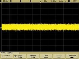
On the other hand, a modern AC-DC current probe such as Agilent’s N2783A 100 MHz probe is capable of measuring 5 mA of AC or DC current with approximately 3% accuracy. The current probe is designed to output 0,1 V per one ampere current input. In other words, the oscilloscope’s inherent 2 mVPP noise can be a significant source of error when measuring less than 20 mA of current.
So, how can the oscilloscope’s inherent noise be minimised? With modern digital oscilloscopes, there are a number of possible approaches:
1) Bandwidth limit filter – Most digital oscilloscopes offer bandwidth limit filters that can improve vertical resolution by filtering out unwanted noise from input waveforms and by decreasing the noise bandwidth. Bandwidth limit filters are implemented with either hardware or software. Most bandwidth limit filters can be enabled or disabled at the user’s discretion.
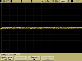
2) High-resolution acquisition mode – Most digital oscilloscopes offer 8 bits of vertical resolution in normal acquisition mode. High-resolution mode on some oscilloscopes offers much higher vertical resolution, typically up to 12 bits, which reduces vertical noise and increases vertical resolution. Typically, high-resolution mode has a large effect at slow time/div settings, where the number of on-screen data points captured is large. Since high-resolution mode acquisition averages adjacent data points from one trigger, it reduces the sample rates and bandwidth of the oscilloscope.
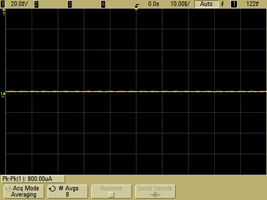
3) Averaging mode – When the signal is periodic or DC, averaging mode can be used to reduce the oscilloscope’s vertical noise. Averaging mode takes multiple acquisitions of a periodic waveform and creates a running average to reduce random noise. High-resolution mode does reduce the sample rates and bandwidth of the signal, whereas normal averaging does not. However, averaging mode compromises the waveform update rate as it takes multiple acquisitions to average out the waveforms and draws a trace on the screen. The noise reduction effect is larger than with any of the methods above as a greater number of averages is selected.
Improving current probe measurement accuracy and sensitivity
Knowing how to lower the oscilloscope’s vertical noise with one of the techniques above, let us consider how to improve accuracy and sensitivity of a current probe. There are a number of different types of current probes on the market. The one that offers the most convenience and performance is a clamp-on AC-DC current probe that can be clipped onto a current-carrying conductor to measure AC and DC current.
Two useful tips for using this type of current probe are:
1. Remove magnetism (demagnetise/degauss) and DC offset: To ensure accurate measurement of low-level current, it is necessary to eliminate residual magnetism by demagnetising the magnetic core. Just as an undesired magnetic field built up within a CRT display would be removed to improve picture quality, a current probe can be degaussed or demagnetised to remove any residual magnetisation. If a measurement is made while the probe core is magnetised, an offset voltage proportional to the residual magnetism can occur and induce measurement error.
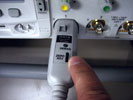
It is especially important to demagnetise the magnetic core whenever the probe is connected to power on/off switching or excessive input current. To perform the probe demagnetisation/degauss, remove the probe from all conductors, make sure the probe is locked closed, and then press the probe DEMAG (or DEGAUSS) button. In addition, a probe’s undesired voltage offset or temperature drift can be corrected using the zero adjustment control on the probe.
2. Improve the probe sensitivity: A current probe measures the magnetic field generated by the current flowing through the jaw of a probe head. Current probes generate voltage output proportional to the input current. When measuring DC or low-frequency AC signals of small amplitude, the measurement sensitivity of the probe can be increased by winding several turns of the conductor under test around the probe. The signal is multiplied by the number of turns around the probe. For example, if a conductor is wrapped around the probe five times and the oscilloscope shows a reading of 25 mA, the actual current flow is 25 mA divided by five, or 5 mA. The sensitivity of the current probe can be increased by a factor of five in this case.
Conclusion
An oscilloscope and a clamp-on current probe provide an easy way to make current measurements without necessarily breaking the circuit. However, when an oscilloscope’s broadband noise is introduced to the measurement, the oscilloscope’s vertical noise can get in the way of making accurate low-level current measurement. By applying one or more of the measurement tips outlined in this article, users can eliminate the oscilloscope’s random noise and the current probe’s undesired magnetism or DC offset to significantly improve measurement accuracy.
| Tel: | +27 12 678 9200 |
| Email: | [email protected] |
| www: | www.concilium.co.za |
| Articles: | More information and articles about Concilium Technologies |


© Technews Publishing (Pty) Ltd | All Rights Reserved
 printer friendly version