


They help users design products that meet their customers’ needs while uncovering defects and producing fully functional products.
Whether it is a student lab station, manufacturing test station or a research and design debug environment, you rely on your oscilloscope on a regular basis, so selecting the right one to meet your needs is an important task. For the economy oscilloscope user, budget is probably one of your most important selection factors. The price of a scope depends on many factors including bandwidth, sample rate, number of channels, memory depth and waveform analysis tools. These factors contribute to the overall value the oscilloscope has to offer. This article discusses five important scope selection attributes.
There are three primary users of economy oscilloscopes. Undergraduate university and primary school engineering laboratories deploy economy oscilloscopes in lab stations for teaching basic electronic and scientific measurements to students. It is here that a future engineer or technician gets their first exposure to how electrical signals behave in a system. For school administrators and professors, it is important to outfit as many lab stations with oscilloscopes as possible given their available budget. More lab stations mean more hands-on time for their students to experience using an oscilloscope, to teach basic electronics principles and troubleshooting techniques critical to their success in industry. Oscilloscopes must be easy to use and provide easy connectivity to enable effective education for students.
Research and design engineers utilise an economy oscilloscope to debug, troubleshoot and characterise their designs from early prototypes through first production run before they are confident it is ready for customer shipments. Not only is it important for the economy oscilloscope to accurately capture the waveform, but engineers often need advanced waveform analysis features beyond basic waveform viewing to get to root cause quickly and easily and meet time-to-market expectations.
Manufacturing process and product engineers architect the production line and repair stations to consistently produce high quality products in volume that meet customer expectations and published specifications. Economy oscilloscopes are commonly deployed along the production line to provide operators with repeatable pass/fail measurements, or at a repair station to debug products that do not pass production tests and minimise scrap. Again, not only is it important for the economy oscilloscope to accurately capture the waveform, but operators need easy operation and quick indication of pass/fail results of products under test. Waveform analysis features are then important at the repair station for highly effective and efficient debug of products that do not initially pass production tests. High turnover rates can be experienced in operator positions, therefore ease of use is an important attribute of an economy oscilloscope when bringing new operators up to speed quickly.
Usability
As technology continues to advance, the economy oscilloscope user can benefit from full waveform viewing with bright, crisp displays. Advanced zoom modes allow for dual display to show the entire memory buffer and the waveform details in the same screen. You get the big picture and the details all at once. An acquisition memory bar shows the location of the zoom in relation to the complete waveform memory when panning and zooming through the capture. Mechanical improvements such as pushable knobs and dedicated colour-coded vertical control knobs make the oscilloscope easy to set up and use, by providing quick access to functions such as setting the waveform position to the zero point on screen.
No matter what area of the development cycle you are using your oscilloscope for debug, user interface can be an important factor in decreasing your testing time. If menus are easy to navigate with pull-out selections and offer quick access to the help menu, you spend less time learning to navigate the scope menus and more time making the measurements needed for device characterisation.
Measure all/FFT
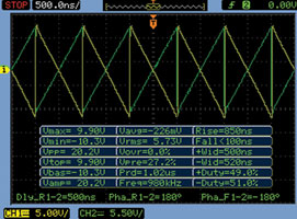
When probing any signal under test, you will want to make certain measurements on your signals, such as peak-to-peak, frequency and rise time. Certain economy oscilloscopes can make surprisingly powerful measurements and offer quite a large number of different types of measurements. For example, the Agilent 1000 series can provide up to 23 automated time and voltage measurements and has the ability to display them on screen at the same time, as shown in Figure 2.
The ability to perform math functions on the signals under test is another time-saving analysis function. Math functions allow the user to gain more insight into problems in the device they are working on by allowing addition, subtraction, multiplication, division, integration, and differentiation of the captured waveforms from the device, and displaying those functions on screen.
Math functions provide a unique learning opportunity for both primary school and undergraduate university students in lab environments. The ability of the oscilloscope to show mathematical concepts in realtime allows the math, physics and engineering departments to work together to show 'real' applications of math in a system. Once the signal and math function are displayed on screen, the student can then experiment with different variations to the signal such as varying amplitude, DC offset and other signal parameters to see the effect in realtime. This is valuable in teaching design principles and the effects of electrical variations on the signal source in the system.
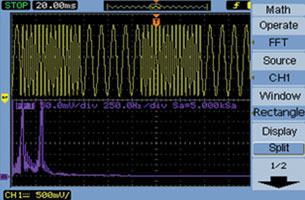
The ability to perform FFT analysis on signals even on the economy scope is especially helpful with amplifiers being so widely used in electronic devices today. Harmonic distortion is a common problem design engineers face, so the ability to characterise a prototype amplifier and view the frequencies that compose your signal allows you to input a sine wave and look at the amplifier output from the device on your oscilloscope by performing an FFT of the sine wave as shown in Figure 3.
Memory and sample rate
Why would more memory be a concern to me when using a low cost economy oscilloscope? There are two main reasons to look for the deepest memory available in the economy scope.
First, memory affects capture time because more memory on the oscilloscope allows the user to view more signal detail. The ability to observe a device’s response over a longer time span allows for an acquisition with more information surrounding the events of interest, which enables more detailed analysis. Second, memory affects the sample rate of the scope. An assumption is often made that an oscilloscope’s maximum sampling rate specification applies to all time base settings. This is not the case. Because of memory depth limits, all oscilloscopes must reduce their sampling speed as the capture time increases. The more memory the oscilloscope has, the more time can be captured at the maximum sampling speed. The required memory depth is dependent upon the amount of time you want displayed, as well as the sample rate you want to maintain. The ability to capture longer time acquisitions while maintaining high resolution sampling requires more memory. In addition, being able to maintain a higher sample rate across all time settings, more memory can help prevent signal aliasing and provide more detail on the signal.
For example, as shown in Figure 4, the Agilent 1000 series oscilloscopes, which have up to 20 000 points of acquisition memory, can maintain high sample rates over a broader range of time base settings.
Mask testing
An oscilloscope should not only provide accurate visual representations of the signal, but also have additional analysis functions to make designing and testing your signals faster and easier. Mask testing on economy oscilloscopes is one such analysis function that can aid in the manufacturing cycle of product and quality test.
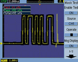
The purpose of the quality and test process is to ensure that products consistently meet performance standards and maintain a low defect rate. To ensure low defect rates, products need to be tested using repetitive testing methods that include a large number of samples. With mask testing functionality on your oscilloscopes, a simple pass/fail mask can be used. You can define a waveform mask based on the current waveform on the screen and specify that any input waveform must be contained within the mask. Acquire a 'golden' waveform and define tolerance limits to create a test envelope. Incoming signals will be compared to the allowable tolerance range and quickly flagged as pass or fail.
Mask testing can be used repetitively to ensure the signals meet the required specifications. This is orders of magnitude faster than manually checking individual measurements on that signal and provides more reliability because the entire signal can be evaluated against a correct signal to find signal anomalies. As a result, mask testing saves time and money by ensuring that customers receive higher-quality products sooner.
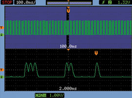
An example of how mask testing works is shown in Figure 5 below where we see an Agilent 1000 series oscilloscope using the automatic pass/fail mask testing function to test a signal to a predefined mask. In this example, the user needed to test 100 waveforms repetitively to determine if the signal meets the required specifications. As you can see, there is a glitch in this particular signal that is causing a failure on the repetitive mask testing. The user can now go back to the device under test and further determine what is causing the glitch in the signal.
Sequence mode
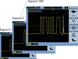
The last feature we will discuss here is sequence mode. This is a very useful feature for maximising the oscilloscope’s memory. In the economy oscilloscope, there is much less memory available for waveform capture than in the higher performance oscilloscopes. One way to maximise memory utilisation on an economy scope is to capture the triggered events in segments into the oscilloscope memory.
This mode is ideal for capturing signals that have periods of burst data in between long periods of dead time. This allows for only the periods of signal activity to be captured and so the scope memory is not used up capturing the dead time between the signals. The signals of interest are then recorded into memory and can be played back to easily spot glitches or other signal anomalies for further examination. For example, on the Agilent 1000 series oscilloscope, you can record up to 1000 occurrences of a trigger event. The waveforms can then be stored to internal or external memory. This is shown in Figure 6.


© Technews Publishing (Pty) Ltd | All Rights Reserved
 printer friendly version