


The first part of this article appeared in Dataweek 5 August 2009.
Power factor correction for modern motor drives
While modern motor drives provide many features and can greatly enhance the efficiency of the motor itself, and can often make the whole system containing the motor more efficient with new features such as variable speed control, there is at least one downside of the new technology. Everything you have learned about correcting the inductive power factor of electric motors using capacitors is irrelevant.
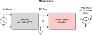
The bad news is that simple capacitive power factor correction schemes used in the past do not work well for modern motor drives. With the new generation of motor controllers, the motor drive electronics appear like a large AC-to-DC power supply when viewed from the power grid. Without power factor correction, these look highly non-linear. A quick look at a motor drive block diagram reveals why.
Motor drive electronics usually consists of two main parts: a rectifier that converts the AC input mains voltage to an intermediate DC power bus and an inverter that converts the DC bus voltage to AC at the motor’s operating frequency and current. In many ways, these two main blocks are duals of each other: one efficiently converts AC to DC, and the other efficiently converts DC to AC. The energy losses in these two blocks, which together seem like a round-about way to go from AC to AC, are more than offset by the efficiencies gained by having more control over the magnetic field phase and the added advantage of variable speed operation.
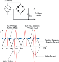
Nearly all single-phase AC-to-DC power supplies have a full-wave bridge rectifier circuit on the input, followed by a large bulk capacitor, which attempts to hold its DC voltage constant between the half-cycle peaks of the input voltage sine wave. Of course, no matter how large it is, the capacitor droops slightly between half-cycles, so when the next peak comes, the rectifier bridge conducts and recharges the capacitor.
The capacitor charging current only flows when the input voltage (less the voltage drops across the rectifiers) is greater than the voltage on the capacitor; when it is less, the rectifiers are off and little or no current flows. Therefore, the current is highly non-sinusoidal, as shown in Figure 4. The low power factor caused by the high harmonic content of the currents causes similar problems for the power company to those caused by sinusoidal reactive power, only worse. The harmonics cause distortion in the voltage waveform, and can even cause destructive resonances in the power grid.
Uncorrected power factors may be as low as 0,5 or 0,6 for this type of rectifier design. A similar situation applies to three-phase mains power, but the rectifier bridge has six diodes instead of four, and the phase peaks six times per cycle instead of twice.
For lower-power systems (less than 100 W), passive power factor correction (PFC) may be used. For these low-power applications, the energy efficiency of passive PFC can be relatively high (up to 96%). A low-pass filter, usually comprised of an inductor, capacitor and resistor, is inserted between the AC mains input and the bridge rectifier. This tends to draw most of the current out of the mains at the line frequency, which is within the passband of the filter. The harmonics of the line frequency are reduced to some degree, and the current waveform is smoothed out. Passive PFC is generally not sufficient for motor control applications due to its marginal performance with respect to the resulting power factor (typically around 0,75), and the large size of the components for higher power applications.
Active power factor correction
Active power factor correction can achieve very high power factors – 0,98 and above – with reasonably sized components, though the energy efficiency may be slightly lower than with passive techniques (eg, 94 vs. 96%) due to the addition of switching components. In one of the simplest architectures, an inductor, a MOSFET or IGBT switch, and a diode are added between the rectifier bridge and the bulk capacitor, in a boost switch-mode power supply configuration.
This is how the AC-to-DC boost converter works: the intermediate DC bus voltage is chosen to be higher than the peak voltage of the rectifier bridge, so the switch-mode controller will be working in boost mode. The controller driving the switch (Q) will adjust the duty cycle of the switch control signal so that the desired current and voltage targets are maintained. The switching frequency is chosen to be much higher than the AC mains frequency (eg, 20 kHz vs. 50 Hz). The small current ripple at the switching frequency and its harmonics can be filtered using a passive filter on the AC mains input, similar to passive PFC, but much easier because of the lower amplitude and higher frequency of the ripple current.
During phase one the switch is closed, shorting one end of the inductor (I) to ground. Current is drawn through the inductor via the rectifier bridge, energising the inductor’s magnetic field. During phase two, the switch is opened. Since the current on the inductor cannot change instantaneously, the voltage on the inductor increases almost instantaneously until it is above the DC bus voltage by enough to turn on the diode (D). The current going through the inductor charges the bulk capacitor (C) as the magnetic field collapses slightly and simultaneously raises the DC bus voltage slightly. All the while, the motor inverter is drawing current from the DC bus in order to power the motor, using up the charge stored on the bulk capacitor and thus reducing the DC bus voltage.
The amount of current drawn out of the AC mains is controlled in a manner such that the short-term average current is in phase with the mains voltage sine wave. Thus, the current through the inductor is controlled so that it approximates a full-wave rectified sine wave, plus and minus the switching frequency components. The average amplitude of the full-wave rectified current is controlled over the long term so that the DC bus voltage is regulated to the target voltage. This means the average current flowing into the capacitor from the rectifier and inductor (when the transistor switch is off) must match the average current going out to the inverter and motor.
Rectifier (with PFC) efficiency
The boost configuration switch-mode regulator with power factor correction can be very efficient. Even though the input current is shunted to ground during phase one, little energy is lost because the voltage drop across the low-impedance switch is small. Most of the energy goes to build up the magnetic field of the inductor, and this energy is recovered and transferred to the bulk capacitor during phase two.
There are small voltage drops across the diodes in the system, but for high-voltage circuits, these are proportionately fairly low. If they become a concern, the diodes can be replaced with low-impedance MOSFETs or IGBTs with lower 'on' voltages than the diodes they replace. These are switched at the appropriate times by the controller (ie, when the voltage across them goes through zero, just like an ideal diode would switch).
There are small energy losses during the switching intervals when the switch transistor is not 'on' enough to have a low voltage, and not 'off' enough to have a low current; so for a brief instant during each transition there are I²R losses in the switch transistor. Also each cycle there are CV² dynamic energy losses caused by charging and discharging the gate capacitance of the transistor. The inductor can have I²R losses due to the DC resistance of its windings. Often, coreless toroidal inductor designs are used to minimise dynamic core losses and allow for higher currents without saturation problems. Finally, the bulk capacitor must have low series resistance and must be reliable under conditions of large switching currents. Like in any switch-mode power supply design, all of these potential losses must be considered and mitigated by careful design and component selection.
Adding options
The basic active power factor correction architecture shown above can be enhanced in a number of ways. One is to adapt it for three-phase AC mains input power.
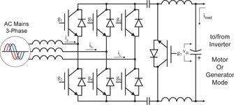
A simple full-wave rectifier for three-phase inputs consists of six rectifier diodes instead of the four in the single-phase bridge. Unfortunately, it is difficult to achieve a good power factor using just diodes, because they only conduct for the half-wave output with the highest instantaneous voltage. For a good power factor, there must be half-wave sinusoidal currents being drawn or returned through all six branches of the input bridge in the correct phase relationship.
One way of solving this dilemma is by using switching transistors in place of the six diodes and controlling them with a pulse-width-modulation (PWM) controller that ensures current is being drawn from each phase, over a short-term average, in direct proportion to the phase’s voltage. As before, the long-term average current is determined by the needs of the motor.
Another enhancement to the whole rectifier/inverter system is to provide for dynamic motor braking, or regeneration. In this mode, the motor inverter sends current from the motor, which is acting in a generator mode, back into the bulk storage capacitor, raising the DC bus voltage. One simple way to prevent the DC bus voltage from going out of regulation is to dump the excess current into a resistive load using another simple PWM controller. Depending on how much momentum is attached to the motor, the amount of energy dumped can be very substantial. This energy is forever lost, and can generate a great deal of heat.
A more sophisticated solution is to modify the rectifier so that it can return the energy to the AC mains. Instead of drawing current out of the mains in phase with the voltage of each phase, the rectifier controller returns current to the power company by inverting the phase of the current so it is exactly out of phase with the input voltage. Even though the current is inverted, it must still have a good power factor in order to be useful. The current should be sinusoidal, exactly out of phase (not reactive), and have low harmonics; in other words, it needs to be like the current that would flow if the load were an ideal negative resistor.
With these conditions met, the sinusoidal out-of-phase current supplied to the mains during braking can be used by some other device in the factory that is consuming in-phase current, reducing the net local power consumption. If there is no other load to use the power locally, the power meter will run backwards as the energy is returned to the power company, where someone else can use it, thus reducing the load on the main generators.
Note that when designed to do dynamic braking with three-phase AC mains, the rectifier is looking almost like an inverter. It is really supporting both modes: power flowing from the AC mains to the DC bus (rectifier mode), and power flowing from the DC bus back to the AC mains (generator or inverter mode).
The simple boost mode switcher presented earlier cannot do all these jobs. Conversely, more complex architectures, such as the Cuk-Cuk boost-buck three-phase rectifier with regenerative capability can do all these jobs and more.12
Another enhancement is for one large rectifier to supply DC power to multiple loads, including possibly several inverters driving AC induction motors, in what is called ‘multidrive’ operation.13 In the debate started over a century ago between Thomas Edison and Nikola Tesla about the relative benefits of AC and DC power, Tesla (who favoured AC) may have ruled with the technology available in the 20th century, but Edison might win in the 21st. More likely, both will coexist, with DC power having a much greater role than in the past.
Control algorithms
Space does not permit a thorough review of either motor control or power factor correction algorithms. One significant observation is that many of the same concepts and algorithms being used in modern motor control have a dual in rectifier control. Terms such as sensorless, observer, space vector control and dq-to-abc transform abound in the literature of both fields.
This translates into creating implementations that require the same types of computational elements, and of approximately the same complexity – at least for the high-end systems – for both motor inverters and rectifiers with power factor correction.
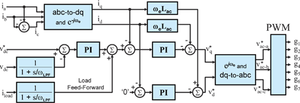
Figure 7 is a block diagram of a controller that uses load feed-forward to provide faster response to load changes than can be obtained by monitoring the DC bus voltage alone, including possibly sudden changes from driving the motor to dynamic braking. The abc-to-dq and e-jwe block, and the e-jwe and dq-to-abc block, transform back and forth between a rotating three-phase frame of reference synchronous with the AC mains voltage, and the stationary orthogonal frame where the proportional-integral (PI) control laws are applied. The pulse wide modulator (PWM) drives the gates of the seven switching transistors in the Cuk-Cuk rectifier.
Implementing a controller
Simple active power factor correction, like simple motor control, can be implemented inexpensively in a number of ways. One of the most common is using a low-end microcontroller. This would be sufficient for DC motors and stepper motors on the motor side, or a simple single-phase boost regulator on the rectifier side. Several companies offer mixed-signal application specific standard products (ASSPs) capable of solving some specific power factor correction problem.
Mid-range systems, such as controlling a single motor at a modest sampling frequency, can be implemented using one of the many digital signal processor (DSP) microcontrollers designed for motor control applications. These often have special functions integrated on-chip to support motor control, such as support for current sensing, comparators and dedicated PWM peripherals. It should be possible to adapt these products to mid-range rectifiers as well.
Things get more interesting when there are special requirements. Then, DSP microcontrollers may run out of steam. Most DSPs are flexible, but inherently they are sequential state machines that can only do a very limited amount of computation in a single clock cycle. As algorithms become more complex, sampling frequencies rise, and higher levels of integration are desired, the DSP solution either fails altogether, or becomes too expensive.
In that case, the ideal solution is a mixed-signal FPGA. These offer many of the special analog functions (such as current sensing) needed for either of the motor control or rectifier problems, plus a configurable logic fabric. Unlike DSPs, the mixed-signal FPGA can do many computations in parallel, and can do certain specialised computations such as computing sines and cosines (which are generally required by these algorithms) much faster than most any DSP microcontroller, at a lower cost per computation.14 As a bonus, FPGAs invariably consume less power than any type of microcontroller doing the same function. This is because only a small part of most microcontrollers is dedicated to doing computations; most of the energy is being used to move data from place to place, fetching the next instruction, and the like.
Mixed-signal FPGAs combine the best features from both worlds: a software driven microcontroller in either soft or 'hard' gates (loaded in the FPGA fabric, or built into the FPGA itself) can be combined with logic dedicated to some aspect of the controller problem loaded into the FPGA fabric. Taking a quote from the BDTi website (BDTi performs various performance and power benchmarks of DSPs and FPGAs.)
“Another interesting aspect of FPGA flexibility is that FPGAs can readily incorporate processors, but DSPs, GPPs, ASICs and ASSPs cannot readily incorporate configurable logic. In BDTI’s consulting practice we are often called upon to help system developers select chips for their next-generation products. In many cases the previous design incorporates a DSP and an FPGA. In some cases, this combination will continue to be appropriate for the next-generation design. But in other cases, there may be strong incentives to consolidate. In these cases, it is more likely that the FPGA will be able to subsume the functionality handled by the DSP than the reverse. This dynamic favours increased adoption of FPGAs.”15
FPGAs offer lots of flexibility. For instance, if your algorithm requires an extra PWM, it can easily be added to an FPGA solution. PWMs pre-built into a DSP or ASSP integrated circuit may or may not perform the PWM algorithm you want, or take into consideration the needs of your power circuitry. With an FPGA, the PWM can be customised exactly to your specifications. An FPGA can be adapted to accept most any type of feedback sensor (encoder, Hall effect, tachometer etc,); or a sensorless algorithm based upon motor back-EMF measurements can be implemented.
Great opportunities for increased integration lie with mixed-signal FPGAs. Probably the most intriguing example is to incorporate nearly all the control functions for both a high power factor rectifier and a motor control inverter in a single device, including many of the analog functions. Another common application would be to have more than one motor controller implemented in a single chip, for multi-axis applications. This is an ideal application for multidrive, with one rectifier supplying two or more motor inverters. A mixed-signal FPGA-based solution can achieve higher sampling rates for highly dynamic or high-precision applications.
References
1. www1.eere.energy.gov/industry/bestpractices/motor_challenge_national_strategy.html (DOE)
3. www.eia.doe.gov/international/RecentTotalElectricConsumption.xls
4. http://re.jrc.ec.europa.eu/refsys/pdf/PV%20Report%202008.pdf
5. www.theiet.org/factfiles/energy/iet-motors.cfm?type=pdf (IET)
6. Ibid (DOE)
7. Ibid (IET)
8. www.mtprog.com/spm/download/document/id/653 (MTP)
9. Ibid (MTP)
10. www.reliant.com/en_US/Page/Generic/Public/esc_purchasing_advisor_ac_induction_motors_bus_gen.jsp
11. www02.abb.com/global/gad/gad02077.nsf/lupLongContent/34269F63260C7505C1256F500038C509
12. www.ece.wisc.edu/~lipo/2001pubs/2001_36T.pdf
13. www.isep.pw.edu.pl/ICG/pdf/phd/mariusz_malinowski.pdf
14. www.bdti.com/articles/fpga_article.pdf
15. www.bdti.com/products/reports_fpga2006.html
| Tel: | +27 11 315 8316 |
| Email: | [email protected] |
| www: | www.asic.co.za |
| Articles: | More information and articles about ASIC Design Services |


© Technews Publishing (Pty) Ltd | All Rights Reserved
 printer friendly version