


Cost pressure, reduction of development times and decreased time to market have led to an increased number of standardised parts. Interfacing subsystems forming more complex devices are common among the automotive and communication industry.
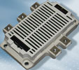
With the new ‘MIPAQ Serve’ shown in Figure 1, Infineon now offers an IGBT module that brings plug-and-play convenience to inverter technology.
The MIPAQ Serve is a six-pack equipped with adapted driver electronics and digital temperature measurement, based on the newly designed EconoPACK4 utilising IGBT4.
The EconoPACK4 advantage
In the EconoPACK4, the power section’s internal construction is designed for increased reliability and improved thermal capabilities. The package, based on the well-known Econo housing principle, is characterised by its flat geometry. As a consequence of the higher power ratings, compared to the EconoPACK and EconoPIM module, the main terminals are built as screw connections. These power terminals feature the so called ‘flow-through’ concept, similar to Infineon’s EconoPACK+. One module side contains the screw terminals for the DC link and the opposite side of the package provides the screw terminals for the AC output connection. The module’s height reduces volume while keeping the mounting procedure simple. A relatively flat inverter structure is the result.
Ultrasonic welding to replace frame bonding is one major step to increase the mechanical robustness. In-frame bus bars form a low inductive interface from the terminals to the semiconductors. The massive copper that is now used instead of bond wires reduces the resistance from the terminals to the DC bus, thereby decreasing the ohmic losses inside the module. Optimised gate driver connection is achieved by placing the driver on top of the module. PressFIT connections between the module and the PCB for the control section further increase the reliability as a gas-tight, low resistive, cold welded connection is achieved.
The MIPAQ advantage
Designing a proper circuit to drive a given IGBT module not only requires choosing components and routing a layout, it also needs to be tested to the full extent to guarantee its function under all relevant operating conditions. This time consuming process is eliminated as the MIPAQ Serve already includes the IGBT driver along with fully digital temperature measurement.
Usually the functionality provided by a gate driver consists of
* Proper driving of the IGBT by applying a sufficient gate pulse.
* Galvanic isolation towards the control electronics.
* Short circuit protection.
* Error signal generation in case of failures.
Upgrading a standard IGBT module to form a plug-and-play solution additionally requires temperature measurement to enable protection from overheating. Furthermore, an interface needs to be included allowing simple but reliable access to the module. An overview of the functional blocks included in the MIPAQ Serve is depicted in Figure 2.
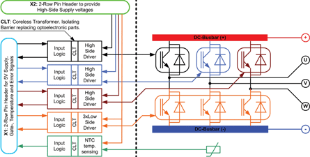
Inside the MIPAQ Serve, Infineon’s 1ED020I12-F IGBT driver is the core component providing all the functionality described above. Galvanic isolation is achieved by implementing coreless transformer technology (CLT). Short circuit is detected utilising desaturation recognition and error signals are generated in case of under-voltage or short circuit.
The internal NTC is used to capture the base plate’s temperature. The signal generated is transported to the logic via the coreless transformer as well, providing a galvanic separation for the temperature measurement. The isolation achieved with CLT today qualifies as functional isolation. Inverter applications, however, demand reinforced isolation which may consist of two functional isolation barriers connected in series. The only action necessary to obtain reinforced isolation using Infineon’s MIPAQ Serve is to add a further functional isolation barrier.
To ease access to the device, the interface consists of connectors according to industrial standards. They are used to connect the gate driver supply voltages as well as the logic supply and control and error signals.
Eliminating optoelectronics
Driver circuits often contain optoelectronic elements that show two major drawbacks: optoelectronic components are known to age over time, especially at higher temperature levels; and the deviation of the propagation delay of commonly used optoelectronic gate driver circuits is in the range of up to 400 ns.
Due to safety concerns, the dead time implemented in many designs exceeds 2 μs to ensure proper operation during the predicted lifetime.
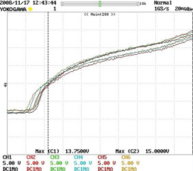
Within the MIPAQ Serve, the deviation between the six IGBT channels is drastically reduced. Turning on the six IGBTs with a single pulse reveals that all six gate voltages are synchronous within a tolerance of less than 20 ns as can be seen in Figure 3.
At turn-off the deviation increases to about 30 ns as displayed in Figure 4.
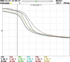
The behaviour demonstrated in these measurements is the key to decreasing the dead time, which is necessary to prevent the risk of short circuit during commutation. Reduced dead times lead to an increase in the inverter’s output voltage, increasing both its output power and efficiency. The inverter’s output voltage can be calculated from the DC link voltage UDC, and the duty cycle D:
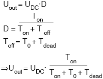
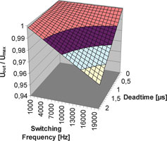
The equation clearly shows that a maximum can only be reached if the dead time Tdead can be reduced to a minimum. The benefit grows along with the switching frequency as the off time includes the product of switching instances and dead time. The influence regarding these two parameters is given in Figure 5 for T0=0:
Conclusion
Building an inverter utilising the new MIPAQ Serve can save cost during the design phase and reduce time to market, while saving space and minimising dead times to help designers boost output power and efficiency. The utilisation of the EconoPACK4 power semiconductor inside the MIPAQ Serve additionally leads to increased robustness and reliability.
For more information contact Davis Moodley, Infineon, +27 (0)11 706 6099, www.infineon.com


© Technews Publishing (Pty) Ltd | All Rights Reserved
 printer friendly version