


GPS (global positioning system) is a satellite-based technology.
It allows users to determine positions at points in time by utilising navigational signals broadcast by multiple satellites, known as a satellite constellation. Currently, this constellation consists of 24 active satellites, which orbit the earth at an altitude of approximately 18 500 kilometres; each satellite completes an orbit every 12 hours. The constellation includes some in-orbit spare satellites which can be activated to replace any satellites which may fail.
The GPS system, known as NAVSTAR, was developed by the United States and is owned and operated by the US Department of Defence. The initial satellites were launched in 1978, and by 1994 a full constellation of 24 satellites was available. Satellites typically last eight to 12 years and new satellites are periodically launched to replace older satellites. Enhancements have been made over the years and currently there are a number of new technologies, including new signals, that are being planned.
Navigation signals
In the current GPS satellite constellation, each satellite broadcasts two different navigation signals, known as L1 and L2. The L1 signal is broadcast on a frequency of 1575,42 MHz, and the L2 signal is broadcast on a frequency of 1227,60 MHz. The L2 signal is encrypted and is available only to authorised users – typically military applications. The L2 signal provides a highly reliable and accurate time and location solution. The L1 signal is not encrypted and is available to users worldwide, 24 hours a day, without charge or subscription. GPS navigation signals are broadcast with circular polarisation – see Figure 1.
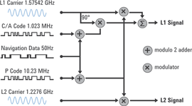
For a given signal (L1 or L2), all satellites broadcast on the same frequency. The signals are differentiated by the different codes that are transmitted by each satellite. This is called ‘code domain multiple access’ or CDMA.
Two different code rates are used. The first code is the coarse acquisition code, or C/A code, which has a code rate of 1,023 MHz and repeats every 1 millisecond. The second code rate is 10,23 MHz, is called the precise or P code and repeats every week. Typically the P code is encrypted to form a code called P(Y). Each satellite is assigned a unique code sequence for the C/A and P codes, respectively. These sequences are identified by a number called the PRN (pseudo-random) ID.
The navigation signals convey information to the GPS receivers including precise timing information as well as system status, orbit descriptions of each satellite and satellite health information. Using this information, a receiver can determine the distance to each satellite and, using a triangulation approach, a position and time can be determined.
Navigation signals are broadcast with a fairly low power and appear at a minimum level of about -155 dBm at sea level. Signal levels may be even lower inside of buildings or under tree cover. These signal levels are extremely low and require significant amplification and baseband processing to recover.
GPS technology
Although GPS receivers have been available for many years, initial implementations were large, expensive and consumed considerable power.
Because of this, the GPS application was limited to high-end commercial and military applications.
In recent years, the cost for GPS receivers has declined significantly for commercial technology. The result is that GPS receiver technology has recently become increasingly important in consumer products such as handheld receivers, automotive receivers, mobile phones and other tracking devices.
Assisted GPS (A-GPS)
A-GPS development was driven by a US FCC E911 requirement to quickly provide a cellphone location to emergency call dispatchers. A-GPS greatly reduces time-to-first-fix (TTFF) measurements and allows GPS receivers to identify satellites at much lower power levels.
‘Assistance data’ is provided by the base station to help the mobile phone identify the satellites that are visible. The mobile phone can then quickly find these satellites and calculate its position. Typical TTFF can be reduced from 60 seconds to under 10 seconds. There are two methodologies for sending and receiving assistance data. They are control plane and IP data channels (user plane).
GPS test requirements
The GPS user experience for commercial applications is affected by several factors. GPS devices which provide an enhanced user experience will sell better, so manufacturers are looking for factors to differentiate their receivers. Typical factors which determine the outcome of the user experience include the following factors:
* When a GPS device is turned on, how long is it until the position of the receiver is determined?
* When a weak or poor signal area is encountered, can the receiver still determine its position?
* If the signal is interrupted and then restored, how long does it take for the receiver to recover and resume calculating its position?
* Accuracy of the calculated location.
There are of course other factors such as cost, user interface, turn-by-turn navigation, spoken directions and so forth that are important to users, but these are not so dependent on the GPS receiver performance.
For commercial or military applications, there may be many other kinds of GPS conditions that are important, such as:
* How accurately can a position or time be determined?
* How repeatable is the solution?
* How sensitive is the receiver to interference or jamming?
* How rapidly can the receiver report its position (if the receiver is moving rapidly, such as in an aeroplane)?
From this point forward, this article will focus mainly on testing for consumer GPS applications.
GPS receiver basics
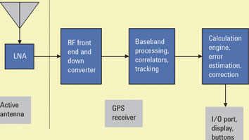
From a high level perspective, the GPS unit appears as an antenna which senses the navigation signals, and has an output of some kind which reports status, positions and time (via some I/O port or a screen). A typical block diagram for GPS receivers includes an antenna, an RF front end/down converter, a baseband processing element and a computation engine. In some cases, these elements may be integrated in a single module which can be quite small – on the order of 1 cm². See Figure 2.
GPS antennas
As previously noted, navigation signals on the earth’s surface are quite low in power. In order to recover the navigation signal successfully, active antennas are typically utilised with gains of 20 or 30 dB. For these active antennas, a DC voltage is supplied from the receiver over the same cable that transmits the signal to the receiver. In most commercial implementations the antennas are integrated into the receiver unit. In some cases a port for an external antenna may be provided.
GPS receiver verification
In order to test a GPS receiver, an antenna can be used to try and receive off-the-air signals. However realistic this approach may be, it can only provide limited information because the signals presented to the receiver are highly variable and non-repeatable. In addition, testing under specific conditions such as remote locations or high velocities becomes expensive and impractical.
To address this issue, a GPS signal simulator may be used. These devices produce an output signal that models the signal that would be received by the GPS receiver – a mix of signals from many different satellites at different time delays, Doppler shifts and power levels. If the proper signal is presented to the receiver, it can perform signal acquisition and tracking and provide a navigation solution (location fix).
Signals can be created by modelling the motions of satellites at a particular point in time. By knowing a specific receiver location (latitude, longitude, altitude), the properties of the navigation signal as it propagates to the receiver location can be modelled and reproduced by a signal generator. These properties can include path losses, distortions due to atmospheric effects, as well as relativistic effects and the effects of transit time as the signal travels from the satellite transmitter to the receiver antenna.
Using a signal simulator with appropriate models, a repeatable, known signal can be presented to the GPS receiver to allow testing to determine the receiver’s ability to operate under various conditions, locations, times and movements.
GPS satellite simulation
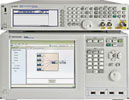
Agilent’s N5106A PXB baseband generator and channel emulator and the N5182A MXG RF vector signal generator combined with the N7609B Signal Studio for Global Navigation Satellite Systems (GNSS) is a solution capable of generating the GPS signals required for comprehensive GPS receiver testing. The N5106A PXB and N5182A MXG combination is a high-performance, general-purpose signal generator that can not only create the required GPS signals, but also signals for other wireless standards such as Bluetooth, WLAN, LTE and WiMAX. The N7609B is a software application with the ability to create and generate custom GPS signals for reliable, repeatable and flexible GPS receiver testing.
Types of GPS tests
Classical receiver testing for digital systems normally involves testing bit error rate (BER, FER, PER, BLER) with specific power, noise, fading and interference conditions. With GPS, one is not only concerned with the recovery of the digital content of the signal, but the receiver must also track the arrival time of the signal very closely (synchronisation).
Correct tracking of arrival times requires tracking the timing of the signal very carefully. In most GPS receivers this is tracked in terms of carrier phase – literally the number of carrier wavelengths and fractions of carrier wavelengths between the receiver and the transmitter. At L1 frequency, this is a resolution of c (the speed of light) divided by the carrier frequency F0 = 1 575 420 000 Hz.
This gives a resolution of fractions of nanoseconds.
Tracking is complicated by the relativistic effects of the velocity between the receiver and each of the satellites. This situation causes a phenomenon known as Doppler shift which means that the receiver perceives the frequency of the signal to be shifted by some amount depending on the relative velocity. So, a receiver has to track not only the timing of the signal from each satellite, but also the Doppler shift of each signal. For receivers that are not moving, the Doppler shift can be on the order of ±5000 Hz.
Further, the data rate for GPS signals is only 50 bits per second, so testing for a bit error rate of 1 error in 1 million bits at 95% confidence would mean running a test that would take hundreds of hours. Clearly something different must be done.
In addition, it turns out that for the GPS receiver, the recovery of data bits is only necessary for short time periods – as little as 18 seconds every few hours. During the remaining time, the receiver just has to track the carrier phase. This means that there are really two sensitivity levels – one for data recovery and one for tracking.
Time-to-first-fix (TTFF)
When a receiver is turned on, it must do some searching to find the satellite signals – this process is called acquisition. It must then track the signals and compute a position. The time from turn on to the availability of the first valid location fix is called time-to-first-fix or TTFF. TTFF is a critical parameter for testing GPS receivers; it relates directly back to a user desire which is to have a location fix as soon as possible.
When testing GPS receivers, one will often hear the terms hot start, cold start, and warm start. These terms refer to the data that is available to the receiver when it is turned on. Most GPS receivers have some persistent memory which stores the time of day and predictions of satellite orbits. When these receivers are turned on, they will use this data as a ‘hint’ to make it easier to search for active satellite signals.
Hot start
If the receiver has been off for a short time (less than an hour or two) and has not moved much (100 metres or less) it will have fairly accurate information on satellites and can typically use this information to acquire satellite signals and compute a position relatively rapidly. This scenario is termed a hot start and may be the case that results from a short power interruption or a battery change.
Warm start
If the receiver has been off for a longer time, or moved farther while it was powered off, it will experience a warm start. With a warm start, the receiver has sufficient data to know what time it is (approximately) but it does not really know where it is.
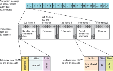
One necessary condition for a warm start is that the receiver has what is known as ‘almanac data.’ Almanac data is a long-term prediction of satellite orbits and is usually pretty accurate for a 24-hour day and deteriorates over the course of several days. Typically, after seven days the accuracy becomes very poor. Almanac data is transmitted by each satellite. It takes about 15 minutes of good signals from at least one satellite in order to receive all the almanac data. This data will be good for several days. See Figure 4 for a description of the satellite navigation message.
For a warm start condition, the receiver has to work harder to acquire the signal, and this means that the TTFF becomes longer.
Cold start
GPS receivers that are started up with no data as to what time it is or where the satellites are located are said to be in cold start mode. In this mode, the receiver’s first job is to acquire satellite signals. In order to do this, it must search each of the available CDMA codes, as well as the frequency space over a range of ±5000 Hz of Doppler shift. This is a fairly difficult task which requires signals of relatively strong amplitude and may take quite a long time. In older receivers it may take several minutes. In newer receivers, the timeframe has been reduced so that it is on the order of 10 to 20 seconds.
With a cold start, the receiver must receive at least 18 seconds of good data from each satellite in order to receive an accurate description of the satellite’s orbit (known as ephemeris data). Once done, the receiver will have sufficient information to compute its first location fix. TTFF for cold start conditions are typically longer than either hot start or warm start conditions. Modern receivers can achieve the TTFF in less than a minute.
Cold start TTFF is an important parameter for GPS receivers and is typically one of the first parameters to test in a GPS receiver.
This article will be continued in the next edition of Dataweek.
| Tel: | +27 12 678 9200 |
| Email: | [email protected] |
| www: | www.concilium.co.za |
| Articles: | More information and articles about Concilium Technologies |


© Technews Publishing (Pty) Ltd | All Rights Reserved
 printer friendly version