


FM radio has witnessed an explosion of interest in applications in mobile and personal media players; however, the traditional FM design approach requires a long antenna, such as a wired headphone, which limits its usefulness and usability.
This article provides a description of an FM radio receiver solution that enables the antenna to be integrated or embedded inside a device’s enclosure, making a headphone cable optional. It covers techniques for maximising sensitivity, including maximising efficiency at the resonant frequency and maximising efficiency across the FM band with a tuneable matching network.
Maximising sensitivity
Sensitivity can be defined as the weakest signal that an FM receiver system can receive while achieving a certain signal-to-noise ratio (SNR). It is an important parameter of FM receiving system performance and is related to both signal and noise. The received signal strength indicator (RSSI) indicates only the RF signal strength at a particular tuned frequency. It does not provide any information about noise or signal quality. The audio signal-to-noise ratio (SNR) is perhaps a better measure for comparing receiver performance with different antennas. Therefore, maximising SNR is essential for listeners to experience good audio quality.
Antennas are the connection between the RF electrical circuits and electromagnetic waves. For FM reception, an antenna is a transducer that converts energy from electromagnetic waves to a voltage that can be used by an electrical circuit, such as a low noise amplifier (LNA). The sensitivity of an FM receiving system is directly related to the electrical voltage received by the internal LNA. To maximise sensitivity, the electrical voltage must be maximised.
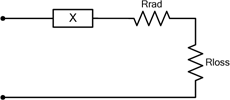
There are a variety of antennas – including headphone, stub, loop and chip antennas – on the market, but all antennas can be analysed using equivalent circuits. Figure 1 shows a generalised equivalent antenna circuit model, where X can be either a capacitor or an inductor. The choice of X is determined by the antenna topology, where the value of the reactance (inductive or capacitive) is related to the antenna geometry. The loss resistance, Rloss, is related to the power dissipated in the antenna as thermal energy. The radiation resistance, Rrad, is related to the voltage generated from the electromagnetic wave. For simplicity, the loop antenna model will be analysed in the remainder of this article. Similar calculations can be made for other antenna types, such as the short monopole and headphone antennas.
Maximising efficiency at the resonant frequency
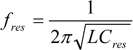
In order to maximise energy from the antenna, a resonant network is used to cancel out the reactive impedance of the antenna, which would otherwise attenuate the amount of voltage the antenna transfers to the internal LNA. For an inductive loop antenna, a capacitor, Cres, is used to resonate the antenna at the desired frequency:
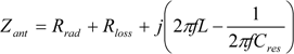
The resonant frequency is the frequency at which the antenna most efficiently converts an electromagnetic wave to voltage. The antenna efficiency is the ratio of the power through Rrad to the total power collected by the antenna and can be written as Rrad/Zant, where Zant is the impedance of the antenna with the antenna resonance network. Zant is written as:
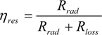
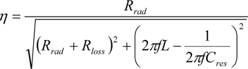
When the antenna is resonated, the efficiency, h, can be defined as:
At other frequencies:
At frequencies other than the resonant frequency, fres, the antenna efficiency, h, is lower than the maximum efficiency, hres, since the antenna input impedance, Zant, is either capacitive or inductive.
Maximising antenna size
To recover a transmitted radio signal, the antenna must collect as much energy as possible from the electromagnetic wave and efficiently convert it into voltage through Rrad. The amount of energy collected is limited by the available space and size of antennas used in portable devices. For traditional headphone antennas, it can be as long as a quarter wavelength of the FM signal, which collects sufficient energy to convert to a voltage that can be used by the internal LNA. Consequently, it is less important to maximise the efficiency of the antenna.
Because portable devices are getting smaller and thinner, the space allowed for an embedded FM antenna is very limited. It is still important to maximise antenna size, but the energy collected by an embedded antenna is small. Therefore, to use smaller antennas without sacrificing performance, improving antenna efficiency becomes very important.
Maximising efficiency across the FM band with a tuneablematching network
In most countries, the FM broadcast band is in the frequency range of 87,5 to 108,0 MHz. In Japan, the FM broadcast band is 76 to 90 MHz and in some eastern European countries, it is 65,8 to 74 MHz. To accommodate all FM bands worldwide, a 40 MHz bandwidth is required for an FM receive system.
Traditional solutions usually tune the antenna at the centre frequency in the FM band. However, as shown in the above equations, the efficiency of the antenna system is a function of frequency and reaches its maximum at the resonant frequency, dropping as the frequency is moved away from the resonant frequency. Again, since the worldwide FM band can be as wide as 40 MHz, antenna efficiency can decrease significantly at frequencies far from the resonant frequency. For example, setting a fixed resonant frequency of 98 MHz gives good efficiency at this frequency point, but efficiency at other frequencies drops significantly, degrading FM performance the further one moves from the resonant frequency.
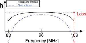
Figure 2 shows an efficiency plot for two antennas (a headphone antenna and a short antenna) with fixed resonance at the centre of the band (98 MHz). From this graph, 98 MHz achieves the best efficiency, but the efficiency degrades closer to the band edges. This is not a significant issue for the headphone antenna since the antenna is large enough to collect sufficient electromagnetic energy to transfer a significant voltage to the RF receiver across the whole band; however, the short antenna is small and collects less energy compared to a longer headphone antenna, and the efficiency also rolls off faster as the frequency moves away from resonance.
This can present a problem for reception at the band edges using fixed resonance. This is primarily due to the fact that a short antenna will likely have a higher ‘Q’ than a headphone, resulting in the sharper drop at the band edges. The quality factor, Q, is proportional to the energy stored in the antenna network to the energy lost or radiated, per unit time. For the above antenna equivalent circuit with an antenna resonated network, Q follows as:
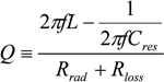
A headphone antenna has inherently higher radiation resistance, Rrad, than a short antenna due to its larger geometry, resulting in a lower Q than the short antenna. The issue of efficiency roll-off is very pronounced with the short high-Q antennas required for embedded implementations. The antenna's Q is also related to the bandwidth of the antenna. This relationship is given as:

where fc is the resonant frequency and BW is the 3 dB bandwidth of the antenna. A short high-Q antenna has a smaller BW compared to a long headphone antenna and increases losses at the band edges.
To overcome the bandwidth limitations of a high-Q, fixed-resonance antenna, a self-tuning resonant circuit is used to change ‘fixed resonance’ to ‘tuned resonance’ so that the circuit is always at the resonant frequency for maximum sensitivity. A higher SNR is achieved with a self-tuning resonant antenna because the gain from the resonant antenna lowers the system noise figure of the receiver, and the inherent high Q of the embedded antenna helps filter interference that could mix with harmonics of the local oscillator.
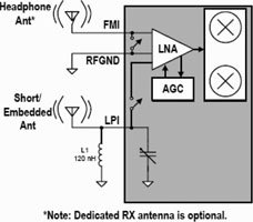
Figure 3 shows a conceptual block diagram of the Silicon Laboratories' enhanced FM receiver Si4704/05 architecture used to support a short embedded antenna. The ‘tuned resonance’ is implemented using a patent-pending, on-chip tuneable varactor and tuning algorithm. The Si4704/05 utilises a patented mixed-signal, digital low-IF architecture with a digital signal processor (DSP) to implement advanced signal processing algorithms including self tuning of short embedded antennas. The antenna algorithm automatically adjusts the capacitance value of the varactor with each frequency tune of the device for best performance.
For example, if the user tunes to 101,1 MHz (Station # 1 in Figure 4), the antenna algorithm will tune the antenna circuit resonance to 101,1 MHz, thus optimising the efficiency of the antenna and the resulting Rx performance at 101,1 MHz. When the user tunes to 84,1 MHz (Station # 2 in Figure 4), the antenna algorithm will retune the antenna circuit resonance such that it is optimised at 84,1 MHz.
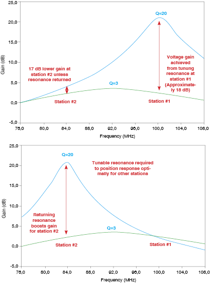
Tuning the antenna resonance with the tuned frequency maximises the received signal strength across the entire FM band by providing the maximum efficiency at each given frequency. As a result of tuned resonance, performance using an embedded antenna is improved across the band. Resonating the antenna at the desired frequency also attenuates interference at other frequencies, significantly increasing the selectivity of the receiver. As a result, consumers using an Si4704/05 FM receiver with an embedded antenna will have less interference from unwanted sources. This is extremely important in urban areas with congested FM frequency bands.
For more information contact Gary de Klerk, NuVision Electronics, +27 (0)11 894 8214, [email protected], www.nuvisionelec.co.za
| Tel: | +27 11 608 0144 |
| Email: | [email protected] |
| www: | www.nuvisionelec.com |
| Articles: | More information and articles about NuVision Electronics |


© Technews Publishing (Pty) Ltd | All Rights Reserved
 printer friendly version