


The size or power density of a power supply is a key criterion when selecting the optimum product for a given application.
In applications where fans are not desirable due to noise or reliability concerns, efficiency becomes of primary concern. Power supply technology has evolved to a point where efficiencies in the 90-95% range are available. To put this into context, a typical power supply in the 1980s would have been in the region of 75% efficient.
A designer, by considering efficiency as an important criteria, can make fundamental design decisions that affect the overall system design in a positive way by:
1) Eliminating or reducing the need for system fan cooling.
2) Reducing the overall size and weight of the system.
3) Reducing the internal temperatures of the system and improving reliability.
4) Enhancing system reliability.
5) Reducing overall energy usage and the end user operating costs.
Size and weight are prime considerations in the selection of power supplies. One can always find a smaller power supply, or design one, by including a fan to provide forced air cooling. A designer might save one-third to one half of the total volume of a typical unit in this way. One disadvantage of this approach is fan noise, which is often restricted in applications such as audio systems, IT applications, medical devices and military systems. Other problems include a significant reduction in reliability – the fan will likely be the only moving part in the power supply, and a maintenance problem is introduced.
In a high-reliability design, the fan will need to be monitored, creating a need for additional circuitry. Due to these issues, many system designers are now looking to utilise convection or conduction cooled power supplies to power their equipment. Minimising component count will help in reducing size and cost, but this has limitations. Equipment must be reliable in a variety of environments meaning that compromises cannot be tolerated with respect to immunity to interference (EMC/EMI/RFI) and production of conducted or radiated emissions.
Finally, one must take account of green legislation including RoHS and CEC/EISA, particularly if equipment is going to be sold around the world. In these cases, the use of RoHS components is obligatory and designing for the highest possible efficiency will not only help in meeting present and future environmental legislation but will also help to ensure best performance from convection-cooled power supplies.
Breakthrough technologies that have a dramatic impact on power supply design are rare. Advances in power semiconductor technology have had the most impact, followed by improvements in magnetic materials and capacitors. Reducing power supply size without compromising performance means that a designer must work towards incremental improvements in every aspect of the design, both electrical and mechanical.
The size – power – efficiency trade off
The surface area available to provide cooling is the limiting factor in how much heat can be dissipated from a convection-cooled power supply (one that does not need a fan). It follows that the more efficient the power supply, the less heat that must be removed and the smaller the unit can be. What may appear to be small differences can have great impact here. If a power supply that is 95% efficient can be bought or designed, versus one that is 90% efficient, the 5% difference in efficiency means that less than half of the heat has to be removed compared to the less efficient design. For a 250 W power supply, this means 14,6 W less heat to be dissipated.
Also, one cannot always rely on a 230 V or 110 V a.c. power source being available, especially for a high-reliability power system that is designed to be used in applications such as military communications running from generators or in countries that have a low or poor AC mains voltage such as 100 V a.c. in parts of Asia. A power supply with a high efficiency across 85–264 V a.c. range is desirable.
Efficiency will also be affected by load – most power supplies operate at maximum efficiency at 80-90% of rated load. It pays to check out the efficiency that can be expected in an individual application. For example, most IT equipment averages at 30–40% of its maximum load in typical operation and the efficiency of the power system will vary accordingly.
The frequency – size – efficiency trade off
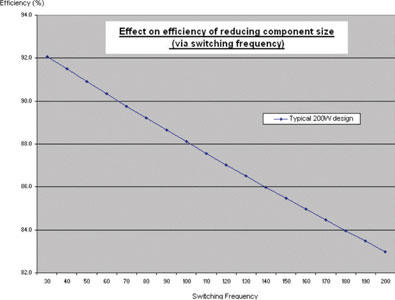
One way to reduce the size of magnetic components and capacitors is to increase the switching frequency of the converter. However, switching losses increase with frequency due to wound component core losses and increased copper/resistive losses caused, in part, by skin effect. The trade off for efficiency and switching frequency in a typical 200 W power supply produced during the last few years is shown in Figure 1.
Clearly, there is a compromise between size, efficiency, switching frequency, reliability, lifetime, cooling technique and, perhaps most importantly, the cost for a given power rating.
Designing for 90%+ efficiency
The best of today’s 250 W, convection-cooled power supplies operate at over 90% efficiency across an input voltage range of 90 to 264 V a.c. This level of efficiency is essential in order to keep within an industry-standard 15 x 10 cm footprint whilst still ensuring adequate heat dissipation without a cooling fan or large external heatsinks.
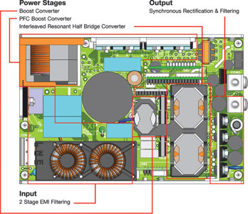
Over 90% efficiency can only be achieved with near lossless switching in the active power factor correction circuit, the main converter(s) and the rectifiers. A diagram for a 250 W AC/DC power supply that achieves up to 95% efficiency at 240 V a.c. input and 92% efficiency at 90 V a.c. input is shown in Figure 2.
From the outset, achieving high efficiency was the primary design goal for this power supply. Consequently, for each stage the power loss budget was determined and this drove the choice of circuit topology. Power losses were minimised in each stage, striving to save every millwatt of unnecessary dissipation. For example, the input filter for the power supply shown above uses very low-resistance winding wire that virtually eliminates I²R losses in the chokes.
A quasi-resonant, lossless power factor correction circuit operates in a discontinuous mode. Its operating frequency changes between 30 kHz and 500 kHz to achieve zero current switching (ZCS) throughout the specified range of loads and input voltages. This is important because it ensures that the voltage switches when the current is truly at zero, thereby eliminating switching losses.
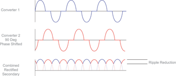
The main converters are of fixed frequency, resonant, half-bridge design – again with lossless ZCS. Two transformers are employed; the combination has lower losses than if one larger transformer had been utilised.
A feedback loop monitors the power supply output and varies the boost converter voltage, which in turn varies the voltage at the input to the main converters. The primary purpose of the boost converter is to boost the PFC voltage of approximately 380 V d.c. to 420 V d.c. This enables the design of the main converters to be optimised around tightly defined voltage parameters, another factor that helps to achieve high efficiency.
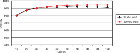
The final stage uses synchronous rectification instead of normal diodes, as this greatly reduces power loss. Timing for the boost converter, main converters and synchronous rectifiers needs to be precisely controlled to achieve accurate ZCS. A crystal-controlled clock is used as the timing reference and a divider network is employed to get the desired switching frequency. Using this approach is crucial for the efficient operation of synchronous rectifiers, especially for higher output voltages. This power supply architecture results in high efficiency across a wide range of loads and input voltages, as Figure 4 demonstrates.
A further benefit of ZCS is the relatively low levels of both conducted and radiated emissions, as well as the output ripple and noise. The power supply referred to above exhibits less than 90 mV peak-to-peak ripple and noise at 20 MHz bandwidth and is below the level B limit line for EN55022 for conducted and radiated emissions. When tested against the stringent MIL-STD 461F CE102 for conducted emissions, this type of power supply passed with considerable margin – opening the door in a range of high-reliability applications without excessive EMI filtering and screening being necessary.
Creative mechanical design
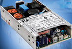
The thermal performance of a power supply can be greatly improved through creative mechanical design. Avoiding hot spots and ensuring the best possible air-flow around components are both important. The power supply described above (XP Power’s CCM250 – Figure 5) has input chokes stacked above other components to save board space. Normally this might create hotspots but the low-loss design of the chokes prevents them.
All heat-generating components, including the power factor correction choke, are bonded directly to the U-channel chassis, which doubles as an effective heatsink, and control circuits are placed on daughter cards mounted at 90° to the main printed circuit board. In other words, full use is made of all the available space by thinking about the mechanical aspects of the unit in three dimensions at the outset of the design.
Conclusion
Combining the best of proven design technologies with creative mechanical design has led recently to the introduction of units that can reach up to 95% efficiency, a figure thought impossible only a few years ago. Further incremental improvements are going to be harder to achieve, but the decades of experience that many engineers now have in power supply design, coupled with advances in semiconductor technology, will make them possible. By considering efficiency alongside cost and size when selecting a power supply, one can improve overall system cost, performance and reliability.
For more information contact Edwin Brown, Vepac Electronics, +27 (0)11 453 1910, [email protected], www.vepac.co.za
| Tel: | +27 11 454 8053 |
| Email: | [email protected] |
| www: | www.vepac.co.za |
| Articles: | More information and articles about Vepac Electronics |


© Technews Publishing (Pty) Ltd | All Rights Reserved
 printer friendly version