


Industrial applications such as the factory floor are typically electrically noisy environments. Electrical noise, either radiated or conducted as electromagnetic interference (EMI), can seriously disrupt the proper operation of other equipment. Insulation protects a cable mechanically from scrapes and abrasion and environmentally from moisture and spills. But insulation is transparent to electromagnetic energy and offers no protection. Shielding is needed to combat the effects of EMI.
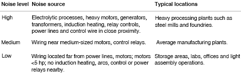
Cables can be a main source of transfer for EMI, both as a source and receiver. As a source, the cable can either conduct noise to other equipment or act as an antenna radiating noise. As a receiver, the cable can pick up EMI radiated from other sources. A shield works on both. Table 1 gives general guidelines as to the areas which are subject to these generalised noise levels. Notice that switching heavy loads, inductive heaters and large transformers can all present high levels of both conducted and radiated EMI. Placing signal cables next to power cables can also allow power-line noise to couple onto the signal lines.
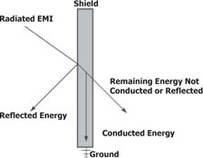
The primary way to combat EMI in cables is through the use of shielding. The shield surrounds the inner signal- or power-carrying conductors. The shield can act on EMI in two ways: first, it can reflect the energy; second, it can pick up the noise and conduct it to ground. In either case, the EMI does not reach the conductors. Some energy still passes through the shield, but it is so highly attenuated that it does not cause interference.
Cables come with various degrees of shielding and offer varying degrees of shielding effectiveness. The amount of shielding required depends on several factors, including the electrical environment in which the cable is used, the cost of the cable and issues like cable diameter, weight and flexibility. An unshielded cable for industrial applications typically is used in a controlled environment – inside a metal cabinet or a conduit, where it is protected from ambient EMI. The metal of the enclosure shields the electronics inside.
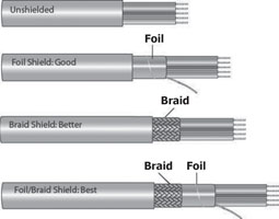
There are two types of shielding typically used for cables: foil and braid. Foil shielding uses a thin layer of aluminium, typically attached to a carrier such as polyester to add strength and ruggedness. It provides 100% coverage of the conductors it surrounds, which is good. It is thin, which makes it harder to work with, especially when applying a connector. Usually, rather than attempting to ground the entire shield, the drain wire is used to terminate and ground the shield.
A braid is a woven mesh of bare or tinned copper wires. The braid provides a low-resistance path to ground and is much easier to terminate by crimping or soldering when attaching a connector. But braided shields do not provide 100% coverage; they allow small gaps in coverage. Depending on the tightness of the weave, braids typically provide between 70% and 95% coverage. When the cable is stationary, 70% is usually sufficient. In fact, one will not see an increase in shielding effectiveness with higher percentages of coverage. Because copper has higher conductivity than aluminium and the braid has more bulk for conducting noise, the braid is more effective as a shield. But it adds size and cost to the cable.
For very noisy environments, multiple shielding layers are often used. Most common is using both a foil and a braid. In multiconductor cables, individual pairs are sometimes shielded with foil to provide crosstalk protection between the pairs, while the overall cable is shielded with foil, braid, or both. Cables also use two layers of foil or braid.
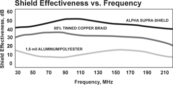
A third approach, seen in Alpha Wire’s Supra-Shield products, combines both foil and braid shields in protecting the cable. Each supports the other, overcoming the limitations of one with its own compensating strengths. As shown in Figure 2, this presents shielding effectiveness superior to either approach alone. Increasing the performance of the Supra-Shield design is the unique triple laminate aluminium/polyester/aluminium foil tape. This tape increases shielding effectiveness through reduced shield resistance and is in contact with a drain wire to facilitate quick and reliable termination.
In practice, the purpose of the shield is to conduct to ground any of the noise it has picked up. The importance of this cannot be overstated – and failure to understand the implications can mean ineffective shielding. The cable shielding and its termination must provide a low-impedance path to ground. A shielded cable that is not grounded does not work effectively. Any disruptions in the path can raise the impedance and lower the shielding effectiveness.
Practical guidelines for effective shielding:
1. Make sure you have a cable with sufficient shielding for the application’s needs. In moderately noisy environments, a foil alone may provide adequate protection. In noisier environments, consider braids or foil-braid combinations.
2. Use a cable suited to the application. Cables that experience repeated flexing usually use a spirally wrapped shield rather than a braid. Avoid foil-only shielding on flex cables since continuous flexing can tear the foil.
3. Make sure the equipment that the cable is connected to is properly grounded. Use an earth ground wherever possible and check the connection between the ground point and the equipment. Eliminating noise depends on a low-resistance path to ground.
4. Most connector designs allow full 360° termination of the shield. Make sure the connector offers shielding effectiveness equal to that of the cable. For example, many common connectors are offered with metal-coated plastic, cast zinc or aluminium backshells. Avoid both over-specifying and paying for more than you need or under-specifying and getting poor shielding performance.
5. Ground the cable at one end. This eliminates the potential for noise-inducing ground loops. A shielded system is only as good as its weakest component. A high-quality cable is defeated by a low-quality connector. Similarly, a great connector cannot do anything to improve a poor cable.
For more information contact Hiconnex, +27 (0)11 315 1909, [email protected], www.hiconnex.co.za
| Tel: | +27 12 661 6779 |
| Email: | [email protected] |
| www: | www.hiconnex.co.za |
| Articles: | More information and articles about Hiconnex |


© Technews Publishing (Pty) Ltd | All Rights Reserved
 printer friendly version