


Power over Ethernet (PoE) controllers for power sourcing equipment (PSE) use high-voltage, high-current field-effect transistors (FETs) to connect the power source to the load.
Integrating the FET devices within the PoE controller reduces the space required to implement the PSE subsystem and also reduces component count.
For example, with a standard TO-223 FET package and two 0805 resistors for current sensing, the external FETs use about 50 mm² of package area per port. When the controller size is added, the package area per port is approximately 70 mm², compared to less than 20 mm² for a typical PoE controller with integrated FETs. Additional advantages of integrating FETs on the PoE controller include higher reliability due to reduced component count, fewer interconnections and guaranteed coordination with the PoE controller fault protection and current limit.
When the FET is integrated, the current sense resistor is also typically integrated, which reduces noise and offset effects and typically allows the use of smaller sense resistors for less current sensing power loss. While the advantages of using the integrated FET are compelling, the reduced size means more care must be taken to avoid excessive heating in both normal and transient conditions. This article takes a closer look at some of the precautions that must be taken when integrating FETs with PoE controllers, using Silicon Labs’ recently introduced Si3452 PoE controller with on-chip FETs as an example.
FET current carrying requirements
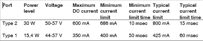
Until recently, the required power level for a PoE PSE system was 15,4 W. The recently adopted 802.3at amendment to the IEEE standard increases the power level to 30 W for ‘Type 2 circuits’ (cat 5E or better cable). The requirements for DC and transient current limit performance, as well as typical current limits, are shown in Table 1. This makes it clear that the FET must be capable of handling high DC current and high transient power conditions.
DC current levels
When using integrated FETs, some care is required because, typically, four or more ports can be supported on one IC. As a result, I²R losses from all ports combine.
For example, the Si3452 4-port PoE controller has a maximum combined FET and current sense resistance of 0,6 Ω. In a worst-case situation, with all four ports carrying 600 mA, the power dissipated is 1,2 W (including Vdd and Vee consumption). The Si3452 is packaged in a 6 x 6 mm QFN with exposed pad. To dissipate this amount of heat, it is recommended that the exposed pad be connected by 25 vias to a heat spreading layer on the back of the PCB with at least 6,45 cm² of copper per IC. With this recommended layout, the thermal impedance is 32°C/W with no airflow, and the worst case rise is less than 40°C.
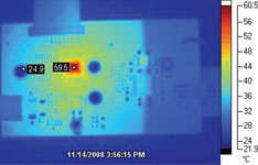
The Si3452 is rated for a junction temperature of 125°C. Therefore, operation at 85°C is possible even without forced air cooling. Figure 1 shows the measured 34,6°C thermal rise of a Si3452 with four ports carrying the worst-case 600 mA.
Transient conditions
The FET must be protected against faults and start-up transient conditions. Normally, the FET source is connected by a current sense resistor to a Vee supply of as much as -57 V, and the drain is clamped to ground. The worst case fault causes 57 V of drain voltage on the FET while it is in the on state. When using an external FET, it is not practical for the PoE controller IC to measure the FET temperature for protection. Therefore, the FET current limit and overload timing (TICUT) must be adjusted to fall within the safe operating area (SOA) of the FET (see Figure 2).
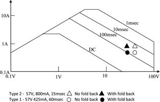
As can be seen in Figure 2, the required current limit and time are very close to the transistor SOA. A special technique, referred to as foldback current limiting, must be employed in this situation. Using this foldback current limit approach, the current limit is reduced as the FET drain voltage increases above a certain level (typically 25 V).
The use of integrated FETs makes it possible to locate thermal sensors close to the FET. The circuitry is arranged to turn off the FET if the thermal sensors activate, providing an additional level of safety against FET damage from fault conditions. Typically, these techniques are combined, resulting in the integrated FET being better protected against fault conditions despite the small size.
One concern with this approach is that a fault on one port might cause a thermal overload indication on another port. This issue can be avoided by placing the thermal sensors near each FET so that severe overloads are detected on a per-port basis. Overloads that are not as severe are protected by monitoring port current and shutting the port off after the required time. Combining these approaches prevents a fault on one port from affecting other ports.
Summary
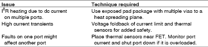
Table 2 summarises the issues with integrating FETs in PoE PSE controllers and the techniques for dealing with these issues in integrated FET controllers. By using the techniques described above, FETs can be safely integrated into PoE PSE controllers, allowing significant savings in cost, component count and required PCB area. Figures 3 and 4 show representative layouts for 12 port comparing the Si3452 with integrated FETs to a 12 port solution without the integrated FETs.
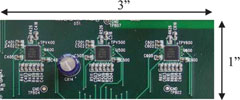
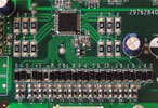
As shown in the comparative photos of Figures 3 and 4, even with the required 6,45 cm² heat spreading layer, the PoE controller solution with integrated FETs occupies less than one half of the PCB area as the layout without integrated FETs – even without using backside components. Integrating FETs on PoE controllers reduces component count, BOM cost and board size, while ultimately enhancing PSE system reliability.
For more information contact Gary de Klerk, NuVision Electronics, +27 (0)11 894 8214, [email protected], www.nuvisionelec.co.za
| Tel: | +27 11 608 0144 |
| Email: | [email protected] |
| www: | www.nuvisionelec.com |
| Articles: | More information and articles about NuVision Electronics |


© Technews Publishing (Pty) Ltd | All Rights Reserved
 printer friendly version