


Some power applications have requirements that are best satisfied by a specific DC-DC converter topology.
Although full consideration of the large number of topologies available could be a daunting task, it is helpful to consider the advantages and disadvantages of the two main topological classes: fixed frequency and variable frequency. A specific comparison is made between DC-DC converters using fixed-frequency pulse width modulation (PWM) and variable-frequency quasi-resonant zero current switching (ZCS).
Fixed versus variable frequency
Of the two, PWM can be somewhat simpler in design, but it inherently trades off efficiency against operating frequency. High-frequency operation has long been recognised as one of the main keys to achieving high-power density – eg, smaller magnetics, filters and capacitors – in switch mode converters. With fixed-frequency switch mode converters, however, switching losses increase directly with operating frequency, resulting in a ‘frequency barrier’ that limits achievable power density. Variable-frequency converters overcome the frequency barrier by having each turn-on and turn-off of the switch occur at zero current. Such converters operate at frequencies in excess of 1 MHz and can achieve power densities considerably greater than low-frequency converters.
A second major difference between fixed-frequency and variable-frequency DC-DC converters is the noise generated by the switch.
Many designers intuitively assume that it is easier to design a filter for a fixed frequency converter than for a variable frequency converter. In actuality, the opposite is true[1]. The perception is, in all likelihood, attributable to the term ‘fixed frequency’, which is actually a misnomer. Both types of topologies, in fact, have frequency elements that are more or less fixed and frequency elements that vary as a function of operating conditions.
Figure 1 compares the waveforms of the current flowing through the main switch of a DC-DC converter. In a module using a quasi-resonant topology, the pulse width, T1, is fixed, while the repetition rate, T2, is variable, and in a module using PWM, the opposite is true; the repetition rate is fixed and the pulse width is variable. Each topology generates characteristic noise spectra. In the variable-frequency design, however, there are no high-frequency components associated with the leading and falling edges of the current waveform, T3, because it is essentially a half-wave rectified sine wave. The spectral content of the variable frequency waveform is lower in amplitude and contained in a narrower band.
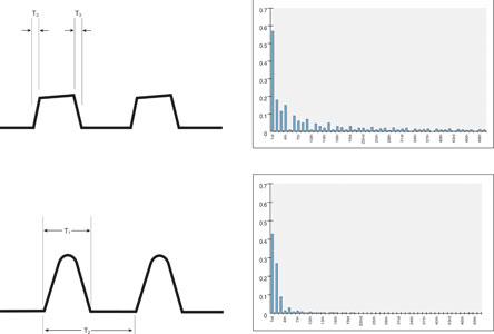
In PWM converters, most of the energy is at the fixed frequency and odd multiples (harmonics) of it. A 100 kHz PWM converter will have most of its conducted noise at 100 kHz and some at 300 kHz and 500 kHz. They also have significant harmonics at or above 10-30 MHz due to the shape of the current waveform, ie, high di/dts that excite parasitic elements within the converter. The input conducted filter has to be sized to handle maximum power at 100 kHz. In the fixed-frequency waveform, the spectral content is higher in amplitude and spread over a broader range of harmonics.
DC-DC converter modules are available that deliver a wide range of features and capabilities regardless of topology. Power conversion topology, however, can be an important consideration if low noise, high power density and constant efficiency are needed.
To take advantage of the potential benefits of these new architectures, topologies and package designs, a designer must understand his or her application as well as the technology. Knowing what is required puts a different light on each attribute and colours what the designer chooses and why. The mundane selection criteria involved in identifying the right DC/DC converter have not diminished in importance. Designers must still define the performance parameters – such as input and output voltages and power, EMI constraints, efficiency, available space – needed to satisfy their application. Depending on the application, time to market, product lifecycle, agency approvals, product cost and cost of ownership may also play a part.
Today, power architectures deserve a more careful look.
Centralised power architecture
A centralised power supply – which can use either PWM or ZCS topologies – contains the entire power supply in one housing, from the front end through the DC-DC conversion stages (Figure 2). It converts the line voltage to the number of DC voltages needed in the system and buses each voltage to the appropriate load. It is cost effective and does no’t consume valuable board real estate at the point of load with the power conversion function. It is fairly efficient because it avoids serial power transformations, and it concentrates the thermal and EMI issues into one box.
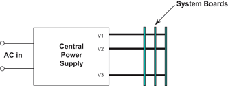
In order to minimise I²R distribution losses, the central supply should be located near the load. For safety and EMI reasons, it should be located as close as possible to the AC entry point. This is often a difficult trade-off.
Distributed power architecture (DPA)
Distributed power (Figure 3) is a decentralised power architecture (that can also use either PWM or ZCS topologies) characterised by bussing a ‘raw’ DC voltage, usually 48 or 300 V d.c. depending on the power source, which is then converted by onboard DC-DC converters located near the loads they serve. Onboard isolated DC-DC converters are matched to the load requirement. This helps with dynamic response and eliminates the problems associated with distributing low voltages around the system.
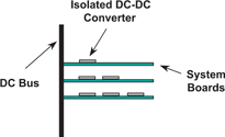
DPA, however, can also be more costly. Since isolation, regulation, transformation, EMI filtering and input protection are repeated at every load, as the loads proliferate, both the costs and board area for power conversion increase.
Intermediate bus architecture (IBA)
To deal with the multiplicity of low voltages more cost effectively, IBA (Figure 4) relies on non-isolated point of load regulators (niPOLs), reducing the POL function to regulation and transformation. The niPOLs (PWM only) operate from an intermediate bus voltage provided by upstream isolated converters. IBA can be a more cost-effective solution because niPOLs, being non-isolated, are less expensive than complete DC-DC converters. But typical niPOL buck converters are in constant conflict between efficient power distribution and efficient power conversion duty cycle.
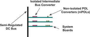
The niPOLs of IBA depend upon a bus converter to provide isolation and voltage step-down from the raw DC bus. This is accomplished by the intermediate bus converter, which is usually either a complete DC-DC converter operating from a wide range DC source, or an unregulated IBC operating from a narrow range input. The conversion to the intermediate bus voltage intrinsically reduces efficiency of the system. Also, the intermediate bus converter really does need to be located close to the load, because, even with a 12 V intermediate bus, four times the current needs to be moved around the board as compared to a 48 V distributed power system, so larger traces or shorter runs are needed.
The 12 V intermediate bus is also too high for efficient conversion to low voltage outputs (<2 V d.c.) as the transformation ratio becomes too high, and the switch duty cycle becomes too low. Lowering the bus voltage to overcome this limitation simply increases the problems associated with the previous issue.
Factorised power architecture (FPA)
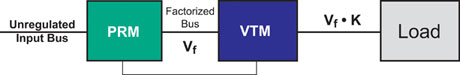
The factorised power architecture uses ZCS and reorganises the basic power conversion functions – voltage transformation, isolation and regulation – and implements them in IC-style packages. A buck/boost pre-regulator module (PRM) provides a stable voltage from an unregulated DC bus, and a voltage transformation module (VTM) steps the voltage up or down and provides isolation at the point of load. High-frequency FPA chips using zero-current/zero-voltage soft switching topologies, offer designers a number of advantages such as small size, high efficiency, low noise and fast transient response combined with extremely high power density (>61 W/cm³ at the point of load).
Figure 5 shows the FPA modules in a basic arrangement, but the PRM and VTM can be operated alone, together, open loop, local loop, adaptive loop, remote loop, co-located, separated, paralleled or combined with conventional power conversion devices (eg, DC-DC converters, point-of-load converters, charge pumps) to achieve the desired power solution.
Reference
[1] L. Hsiu, M. Goldman, R. Carlsten, A. Witulski and W. Kerwin, 'Characterisation and comparison of noise generation for quasi-resonant and pulsewidth-modulated converters', IEEE Transactions on Power Electronics, Vol. 9, No. 4, July 1994.


© Technews Publishing (Pty) Ltd | All Rights Reserved
 printer friendly version