


If a cable fails, it can be quite an undertaking to remove it, replace it and refit it with connectors.
That is why specially insulated cable that resists damaging spikes is useful in demanding variable speed drive (VSD, also known as variable frequency drive or VFD) applications.
Increasingly common, VSDs are used to control motor speed, elevating the frequency of power pulses per second fed to motors for faster turning, and decreasing that frequency to make them turn more slowly. As for the motors controlled this way, they work best when power pulses are well regulated and current is injected in a flow optimal for sustained speed and acceleration consistency. However, VSD conversion of AC to DC to variable AC is not perfect, and introduces non-linear spikes, wave reflections, inrush currents and other signal mutation. The current from this non-linear power does not support motor requirements, because change in voltage does not generate the same change in current; the distorted current either undermines or exaggerates the voltage change, resulting in high voltage stress and heat.
What is worse, connecting cable can actually magnify these signal imperfections. To address this problem, some VSD connections include unshielded tray cables (consisting of single conductor lead wire installed in conduit) or welded armoured cable. But armoured cable and lead-wire conduit are heavy, difficult to install and necessitate huge bending radii — and they do not completely solve noise and corona discharge problems, or effectively address VSD noise issues. On the other hand, well selected motor and control features coupled with specially insulated cabling minimises VSD distortion without the fuss.
Switch spikes and cable length
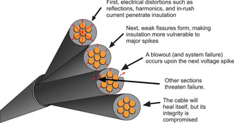
For a rectified 460 V system, a drive’s inverter – a fast-switching transistor – must rise from zero to 650 V and then go back to zero 20 000 times each second. This results in a very fast rise time. Several things can happen as the inverter switches and sends its pulses through the cable to the motor. The 650 V normal voltage can overshoot (spike) by 2000 V or more. Even though these voltage spikes are very quick, lasting for only a few millionths of a second, they can cause considerable damage as power distortions created by VSD rectifiers are sent back through source power systems.
Long cable exacerbates the issue: greater lengths make for greater inductance and higher voltage-spike overshoot, so long power supply cables have more numerous and more intense voltage spikes than shorter cables. Why is that? Long cables connecting motors to drives give a reflected standing wave more opportunity to go into phase with itself, thereby doubling voltage and current (similar to a wheel that appears frozen when actually in motion, reflected frequency waves look electrically to be standing still.) These standing waves can cause damage if they bounce off the large impedance difference at the cable motor attachment and reflect back to the drive. So standing waves can easily turn 650 V into 1300 V. At the spot in the cable where this happens, insulation is severely stressed, can eventually overheat and might even result in puncturing, causing the cable to fail.
Minimising spiking
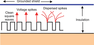
The typical conductor inside a VSD cable is between 3,5 mm² and 35 mm² and is rated for 1000 V and 3000 V peak so that it can withstand reflections and standing waves. VSD cable is also standardised for these conditions. Cable designed specifically for use with VSDs differs from ordinary motor power supply cable in that it disperses spikes that VSD drives generate. A semi-conductive layer relieves electrical stress experienced by VSD cable during high-voltage spikes.
VSD cable construction includes semi-conductive composite insulation applied over the conductor. This inner jacket provides an additional layer of protection between the insulation and braid shield, and lowers the capacitive interaction between the braid and power conductors. The semi-conductive layer disperses rapid voltage rises to protect the primary insulation from damage, letting the cable operate without a disruption in service. PVC-insulated VSD cables typically include an extruded thermoplastic semi-conducting layer applied directly over conducting copper strands. Also, the inner semi-conductive jacket of some cables is sized to fit into a shielding connector for full 360° shield grounding.
Semiconductor-insulated cable protects motors as well. Windings are the delicate part of the motor; their lacquer insulation is extremely thin, and any flaws under shock can cause arcing and motor failure. But motor life is improved about 6% when connected to VSD cables, which reduce both the number and magnitude of reflected waves with their improved impedance.
Harmful harmonics
Some power distortions are caused by harmonic frequencies, multiples of a system’s fundamental frequency. Harmonics, though they rotate more quickly due to their higher frequency, can be in phase with the fundamental frequency and rotate in the same direction as its field; this condition allows harmonics to contribute energy. Only power in the fundamental frequency is needed or wanted; power from harmonic frequencies makes for overheating, high-voltage stress and can confuse electronic functions that depend on the fundamental frequency for clock or timing windings. This higher flow of power pulses can cause motors to run too fast as well, so the presence of harmonic frequencies necessitate that motor movement be fine-tuned with braking and other (heat-generating) reactions.
VSD drives commonly generate 5th, 7th, 11th and 13th harmonics. So say we have a system with a fundamental frequency of 60 Hz, as supplied in the United States – its 5th harmonic is 5 x 60 = 300 Hz. The 5th (and 11th) harmonics oppose the field’s rotation and require additional current (which is unfortunately accompanied by heat) to correct sluggish motor speed. This AC power includes one positive and one negative voltage and current power pulse each frequency cycle. The 7th and 13th harmonics rotate with the field, and supply additional power pulses, and so require braking to correct overly fast motor speed. The 3rd, 9th and 15th are triple harmonics that do not rotate, but are highly in phase and add to neutral current and accompanying heat in the cable.
Reducing harmonics
Changing the pulse rate or switching the drive inverter transistor to a slower frequency can eliminate the low-order harmonics of high electrical power. Also, filters, reactors and isolation transformers can be added to lop off harmonics and block spikes. Designers must keep in mind, however, that these add-ons do cause voltage drop between power supply and motor.
If these measures are taken, cable is left the weakest link in a VSD system. That is why since 1996 National Electrical Code Article 430-22a has specified that source-power cable conductors must be sized at 125% of the full load current of the drive. This requirement protects cables from power distortions generated by the rectifier and ensures safe and uninterrupted operation. This ensures that the cable will not fail due to power distortions — so the whole system is able to handle the type of power that a VSD drive generates.
Stressful starting
Ask anyone who has ever touched an electrified fence by accident, and they will tell you: current can make you go stiff in a hurry. A sudden inrush of current has the same effect on motor windings: Upon startup, they briefly tremble before stiffening into operation, enough of a trial for the delicate insulation on the winding wires as it is. Add exaggerated startup inrush current and the situation can quickly become dire for those copper threads of life.
A motor and its power cable can act as a large capacitor that must be charged up to the normal operating power level. So when a motor is first energised, it can draw up to six times its full-load running power requirements. When the current from the power-pulse source ends up in the power pulses of another circuit, capacitive coupling takes place due to changing electric field in the source circuit. The change in voltage (from zero to full and back to zero) causes current to flow and couple from one copper conductor to another. In short, power pulses from one circuit are added to compatible pulses of another circuit, resulting in heat and stress.
Addressing inrush current
One way to ensure inrush current is not an issue is to install filters that lower inrush currents for more gradual drive startups. Another approach is to use VSD motors, which are double insulated to withstand distorted power and to prevent any penetrating nicks in the winding insulation. In fact, failed motors are often those not replaced during a system upgrade in which VSDs replace plain drives.
Because a motor can draw up to six times its full-load running power when energised, cable must be of adequate conductor size to prevent significant voltage drop. This is also an area where the improved impedance of VSD cable means inrush current shocks less, and makes for less wear and tear on delicately coated motor windings.
From outlet to motor
Besides ancillary resolver and encoder feedback devices, tachometers, sensors and relays, drive systems have four major power parts: source power, VSD, cable and motor. Local electric companies provide source power. It may go through transformers that increase or lower voltage, but its frequency remains a constant 60 Hz.
Power processed by traditional VSDs goes from AC to DC, then into a shaped AC form. Drives reshape power that goes in to control motor startup, operating speed and stopping. Prior to turning the motor at a set speed, source power must be converted from AC to DC by means of a rectifier. This AC-to-DC conversion is necessary before the power can be shaped into a variable frequency signal. A diode is used for simple rectifying or silicone controlled rectifiers (SCRs) are used for more intelligent rectification. Rectifiers convert incoming 60 Hz AC to DC, and multiply that voltage by 1414 — so 460 V a.c. becomes 650 V d.c.
The next component that power encounters on its journey to the motor is a large capacitor, known as the DC bus. Capacitors store energy, and DC buses act like batteries to hold and then flush energy out (as DC power) to the next part of the drive, the inverter. Inverters convert DC back to AC with an electronic component known as a bipolar transistor. The inverter is controlled to vary output frequency so that the motor receives the correct flow of power pulses. Insulated gate bipolar transistors (IGBTs) are one of the fastest-switching inverters in pulse width modulation (PWM)-type VSDs.
What is the advantage of utilising VSDs? Their PWM frequency is about 20 000 Hz and offers quite fine control by varying just a few cycles. In contrast, changing a few cycles at 60 Hz is a much coarser change – and does not allow for close control.
Mi corona
Engineers discovered about 50 years ago that simple conductor/insulation/ shielded cable is voltage limited – and is a safety and reliability concern if used beyond modest limits. The problem arises where conductor meets the primary insulation layer: voids there form where insulation does not fully penetrate the small spaces of the stranded conductor’s outer layer. This literally leaves room for high voltages to ionise the nitrogen in the air trapped in these pockets. Called corona, this discharge across these voids quickly deteriorates insulation. Another problem, especially in the early days of cable, was the small diameter and surface irregularities of individual wires in the outer conductor layer, which produced points of high electrical stress and rapid insulation deterioration.
To address corona, the semi-conductive compounds in VSD cabling also resolves corona problems, acting as a stress relieving layer between the conductor and primary insulation. Common shield types include inner PVC jacketing, overall foil with tinned copper braid, corrugated copper tape and foil on individual pairs.
Failure not obvious
VSDs typically have self-diagnosis programs and shorted motors are easily detected. But cable is hard to test. The voltage spikes that damage them only last a few millionths of a second, and are seldom recognised at the time of actual cable failure; usually equipment just drops offline, which is not a symptom with much diagnostic value.
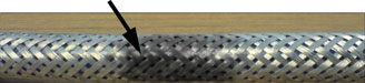
Restarting is usually possible if cable damage is not severe enough to prevent system operation. But when a cable’s insulation is punctured from high voltage stress, the current travels through the hole to the nearest ground path, which is usually the braid shield. When the current from a live conductor finds a grounded braid, huge current is created – too much, in fact, for the shield to carry it away fast enough. So the braid heats up and burns as long as the current can arc to it. Once the hole in the braid is burned big enough, the cable self-heals until the next high-voltage stress puncture occurs at a different spot.
Eventually, when this arcing finally burns through the conductor, cable damage can be detected by ordinary testing. But by then, significant time can be lost checking perfectly healthy motors and drives.
Conclusion
Often with the adoption of new technologies, one tends to forget the most basic components, and in this case many still rely on ‘standard cable’ to connect new high technology worlds, often without fully comprehending the effect that this may have on the connected equipment, or on the unsuspecting fieldbus network that happens to be in the same vicinity.
About the author: Grant Joyce started his career as an instrumentation technician at AECI in Modderfontein. He then spent 15 years in the process control and automation field, two years in the connection solution industry and five years in product management. For the last 10 years, Grant has worked in marketing and sales management.
For more information contact Grant Joyce, Lapp Kabel, +27 (0)11 201 3200, [email protected], www.lappcable.co.za


© Technews Publishing (Pty) Ltd | All Rights Reserved
 printer friendly version