
Current sensors are essential components in many power delivery systems such as AC-DC and isolated DC-DC switch mode power supplies (SMPS), motor control and electronic lighting. As power supply manufacturers strive to increase the power density and reliability of their products, ‘green’ energy mandates are simultaneously driving the need to increase energy efficiency. System designers are consequently demanding smaller, more efficient and higher performing current sensors. Power system designers must assess a variety of design considerations – board size and component size, BOM cost, noise immunity, bandwidth and cost – in selecting the optimal AC current sensor solution for their application needs.
AC current sensor overview
The most common types of AC current sensors found in SMPS systems include current sense transformers (CTs), differential current sense amps, Hall effect devices and direct current resistance (DCR) and low-side field-effect transistor (FET) sensing. The devices are commonly used to protect against over-current conditions and/or provide current feedback information.
Current transformers use transformer action to reflect the current flowing from its primary to secondary circuits, where it is converted to a voltage by an external burden resistor. CTs have gained wide acceptance because they use a minimum number of external components, provide inherent isolation and are inexpensive. However, they are bulky magnetic components that contribute significant supply losses and have parasitics that complicate system design. In addition, they often require additional circuitry for core reset. Many small CTs are still hand-wound, and suffer from mechanical integrity issues such as poor lead spacing uniformity.
Current sense amps generate a voltage signal representative of current by measuring the voltage across a low-value series resistor. The resistor obviously creates power loss that grows more objectionable as current increases, and the amplifiers typically have relatively low bandwidth to limit noise. These characteristics make this technology best suited for low-current DC and low-frequency AC systems, and are often inappropriate for higher-frequency and higher-current switch mode applications.
Hall effect and magneto-resistive (MR) devices operate by sensing the magnetic field generated by a current-carrying inductor and, consequently, offer low power loss. However, these devices tend to have low operating bandwidth, large size and high cost. They also tend to have small, noisy output signals and offset and temperature errors that degrade measurement accuracy.
Low-side FET and DCR sensing circuits both sense the voltage across a resistance already in the circuit, so they add virtually no loss of their own. In the case of DCR sensing, an RC circuit across the output filter makes the combined circuit appear as a resistor. An amplifier connected across this ‘virtual resistor’ measures current the same way as the resistor/sense amp scheme series described earlier. Like DCR, low-side FET sensing also measures the voltage across a resistor, but uses the low-side transistor RDS(ON) as the sense resistor. While both methods use a relatively large number of commodity op-amps and passives, they remain among the lowest-cost, lowest-loss techniques in use today. On the down side, these approaches suffer from large installed size and sometimes require the added cost of system calibration to address high measurement error – sometimes as high as ±40%.
The Si850x/1x AC current sensors from Silicon Labs provide a reliable, efficient and cost-effective alternative to CTs, current sense amps, Hall effect devices and DCR/ low-side FET sensing for today’s modern power delivery systems. Manufactured in mainstream CMOS technology and packaged in a tiny QFN, these highly-integrated sensors have 1 kV isolation and require no external components other than a VDD bypass capacitor.
Offering low series resistance and inductance, combined with high accuracy, the Si850x/1x current sensors enable designers to maximise the efficiency of their power systems. In full-bridge applications, a single Si851x device can replace two current transformers and their associated BOM components. With 5 kV isolation versions packaged in a 16SOW, the Si850x/1x family can be used in virtually any universal powered systems including AC-DC switching power supplies, motor control and electronic ballasts for lighting.
The Si850x/1x series of AC current sensors operate much like a CT. They have on-chip reset circuitry and other active circuits that condition and amplify the output current signal. These devices operate over the frequency range of 50 kHz to 1 MHz.
The Si850x/1x (shown in Figure 1) consists of a metal slug and silicon die housed in a package as small as a 4 x 4 x 1 mm QFN. The slug and on-chip pick-up coil together form a coupled inductor. AC current flowing through the slug induces a voltage into the pick-up coil equal to the first derivative of current (ie, v = Lm di/dt).
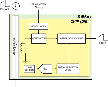
On-chip signal processing circuitry then performs a finite integral operation, resulting in a real-time signal directly proportional to the current through the slug. The resulting signal is further conditioned by an on-chip temperature compensator and gain stage.
The device outputs a 2 V full-scale current waveform with an accuracy of ±5% of measurement. Low-loss operation is achieved because the slug adds 1,3 mΩ of series resistance and 2 nH of series inductance in the current sense path while output noise is minimised by the averaging action of the integrator, eliminating the need for an external resistor-capacitor (RC) filter. Reverse current flow (ie, current flowing from IOUT to IIN) results in a zero output reading and will not damage the device.
The finite integral action requires the integrator to be reset prior to the start of each current measurement cycle. This is accomplished by connecting existing gate control signals to the Si850x/1x reset input pins (R1-R4). The timing criterion for resetting the integrator is simple: the reset event should begin immediately after current measurement and must end prior to the start of the next measurement. For rated accuracy, this reset event should last a minimum of 150 ns. On-chip integrator reset logic provides flexibility to allow the sensor to be used with virtually any power system topology.
Figure 2 shows the reset circuit for the single-output Si850x, which can typically be used in relatively simple applications (ie, buck, boost) where transformer flux balance control is not a design issue.
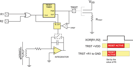
On-chip reset circuits
As shown in Figure 2, integrator reset can be controlled in real-time by signals on R1, R2 when the TRST input is connected to VDD. To accommodate high frequency and/or high duty cycle applications, reset time can be shortened by connecting TRST to ground through timing resistor RTRST. In this case, the start of reset is triggered by R1, R2, but the duration is set by the value of RTRST, allowing the user to trade off sensor accuracy for faster operation. The Si851x products are meant for more complex topologies such as a full-bridge application, where control or monitoring transformer flux balance is important. The more complex reset logic (Figure 3) is a superset of that shown in Figure 2.
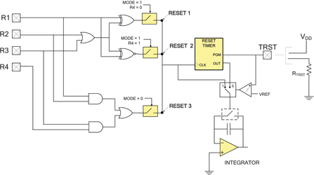
One of three reset algorithms (XOR, XNOR or AND/OR) can be selected, depending on the states of the MODE and R4 inputs. Again, the reset event can be determined by the reset inputs alone or triggered by the reset inputs and timed by RTRST as previously described. In general, RESET 1 is used for boost, isolated and non-isolated buck and other relatively simple topologies; RESET 2 is typically used for push-pull applications and RESET 3 is for full-bridge applications.
Full-bridge application
Figure 4 shows a phase-shift modulated full-bridge application using the Si851x operating in ‘ping-pong’ output mode, which enables a single device to replace two CTs (typically used to monitor transformer flux balance). Ping-pong output mode routes current signals from each leg of the bridge to separate output pins.
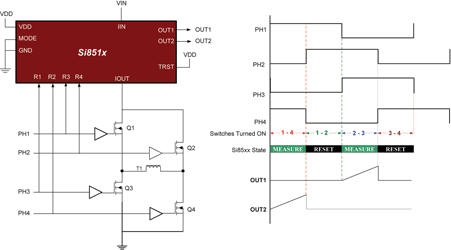
Measured current flowing when Q1 and Q4 are on appears on OUT2; current flowing when Q2 and Q3 are on appears on OUT1. Integrator reset occurs during the current circulation phase (ie, when Q1 and Q2 are on, or Q3 and Q4 are on). The relatively low-frequency operation of the full-bridge allows ample reset time, so TRST is tied to VDD, causing reset time to be a function of the states of R1-R4.
Extending full-scale range
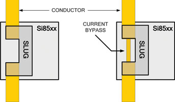
AC current measurements beyond 20 A can be realised using the circuit board layout modification shown in Figure 5. The image on the left is an ‘X-ray view’ of the Si850x/1x mounted on a circuit board, where all of the current flows through the slug. The image on the right adds a small current bypass trace in parallel with the slug, forming a current divider where the width and thickness of the bypass trace determines the current divider ratio. For example, a 1 mm wide trace shunts enough current around the slug to increase Si850x/1x full-scale 1,8 times to 36 A.
For more information contact Gary de Klerk, NuVision Electronics, +27 (0)11 894 8214, [email protected], www.nuvisionelec.co.za
| Tel: | +27 11 608 0144 |
| Email: | [email protected] |
| www: | www.nuvisionelec.com |
| Articles: | More information and articles about NuVision Electronics |

© Technews Publishing (Pty) Ltd | All Rights Reserved