


Part 1 of this aricle was published in Dataweek 16 March 2011.
Operating power
At a minimum, optocouplers require current to bias the LED and some form of bias on the output side. The total input plus output current varies widely, depending on the type of optocoupler.
When forward biased, the optocoupler LED is low-impedance, and device power consumption increases with LED forward current, which can range from 1 mA to over 15 mA. In some cases, the LED may require an external driver, further decreasing system efficiency while increasing BOM complexity and cost. The optocoupler output impedance can be low or high depending on its architecture.
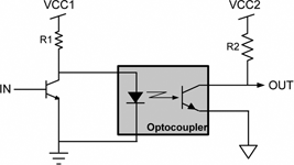
Most low-cost optocouplers have a simple transistor output that is high-impedance when LED forward current is at zero and relatively lower impedance when LED forward current is in its specified operating range. Other (usually higher-speed) optocouplers have an active photocoupler and output driver that requires an external bias voltage. Such devices have low output impedance but at the expense of increased total operating current, which can range from 15 mA to over 40 mA.
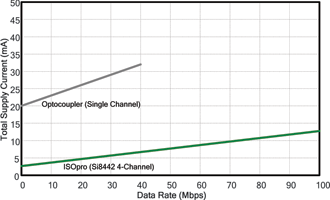
Compared to optocouplers, ISOpro isolators offer significantly higher operating efficiency, consuming approximately 1,7 mA per channel at 10 Mbps at VDD = 5,0 V with a 15 pF load. Their high-impedance input buffer consumes only microamps of leakage current while their 50 Ω CMOS output driver can source or sink 4 mA. The bulk of the ISOpro isolator’s power savings results from the use of an RF carrier instead of light, eliminating the power-hungry LED.
Losses in the isolation path are minimised by the isolation capacitor structures, which are optimised for robust data transfer and minimum power loss. ISOpro isolators’ power dissipation remains relatively flat and substantially less than that of the optocoupler. The only noteworthy contributor to increased supply current is increased data rate, yet even this increase is relatively shallow as shown in Figure 3.
Timing characteristics
Timing specifications are important in digital isolator applications to ensure proper and consistent system operation. Figure 4 compares the propagation delay characteristics of the 10 Mbps ISOpro isolators with those of a competing digital optocoupler. Propagation delays were measured with different LED currents, both with and without a ‘peaking’ capacitor. The peaking capacitor in this case is 20 pF in parallel with the LED current limit resistor. This capacitor momentarily increases LED current during turn-on and turn-off for faster optocoupler response.

In Figure 4, curves B and C show propagation times for LED currents of 0,5 mA and 1,0 mA and no peaking capacitor. As shown, a 0,5 mA decrease in LED current results in a 50% increase in propagation time (80 ns to 120 ns) at 20°C, demonstrating the large timing variations that result from changes in LED current and/or wear-out. Propagation delay is not symmetrical; curve A shows a high-to-low transition fastest propagation time of roughly 35 ns at 20°C, but the low-to-high transition is twice the propagation delay time. Therefore, a system using this component must take into account these asymmetric delays and provide additional timing margin.
While this example demonstrates the changes in propagation time, it is important to note that other optocoupler timing parameters, such as pulse width distortion, channel-to-channel matching, rise and fall time, etc, will follow the same trend because all timing behaviour, including LOP effects, is related to LED emission.
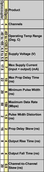
Unlike the optocoupler, the ISOpro isolator’s timing parameters are a function of internal precision timing circuits and fixed propagation delays within its signal path. All timing parameters vary only slightly with changes in VDD, and all remain flat over temperature. For example, rise and fall times vary by only 1 ns across temperature and supply voltage, and worst-case propagation time is approximately 9 ns at 120°C. Table 3 shows the operating characteristics of a 50 Mbps optocoupler compared to the ISOpro isolator.
Common-mode transient immunity (CMTI)
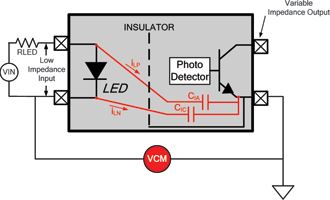
Common-mode transients are one of the leading causes of data corruption in isolation applications. CMTI is commonly measured in kV per microsecond and refers to the ability of an isolator to reject noise that is present between the isolator input and output. Figure 5a shows an optocoupler subjected to common-mode noise, VCM. As VCM changes due to fast transients, iLP and iLN either aid or oppose the LED current, causing a momentary change in LED light emission, often in spite of the detector shield added by manufacturers to reduce parasitic capacitive input/output coupling.
The optocoupler parasitic coupling between grounds is typically in the range of tenths of picofarads, which greatly decreases CMTI. Some degree of CMTI improvement can be obtained using the ‘quasi-differential’ drive shown in Figure 6, where LED current-limiting resistors are placed on both sides of the LED, each having half the value of RLED in Figure 5.
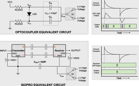
As shown in the optocoupler timing diagram of Figure 6, a positive-going ground transient on the optocoupler’s right-side ground (with respect to the left-side ground) causes a momentary increase in LED current. This LED ‘glitch’ can cause data errors, depending on the magnitude of the transient and the amount of parasitic coupling present in the optocoupler. For example, a 0,6 pF coupling may be sufficient to erroneously turn on the LED momentarily when it should remain off.
Likewise, a negative-going transient can erroneously turn off the LED when it should remain on. The inherently low CMTI of optocouplers is discussed at length in application manuals issued by optocoupler manufacturers, some of which recommend over-driving the LED while in the on state and reverse-biasing the LED while in the off state when operating in high common-mode environments. While this technique is effective, it increases LED power dissipation and hastens the wear-out due to LOP. In any case, the parasitic coupling is unavoidable and degrades optocoupler CMTI performance.
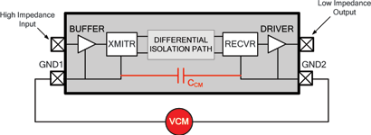
The bottom graphic of Figure 6 shows the ISOpro isolator with its common-mode voltage, VCM, and its 100 femtofarad input-to-output capacitance (CCM), which is six times smaller than that of the optocoupler. Its fully differential isolation path rejects common-mode voltages, and the high selectivity of the receiver rejects all but the carrier frequency for even greater noise immunity. For these reasons, the ISOpro isolator has a typical CMTI of 25 kV/μs, substantially higher than most optocouplers using external components to improve CMTI.
RF immunity
RF immunity is the ability of the isolator to reject strong local electromagnetic fields, thereby maintaining error-free data transfer. Intuitively, one might assume that ambient RF fields would interfere with the ISOpro isolator’s internal RF data transmission. However, ISOpro isolators demonstrate an extremely high degree of external RF noise rejection by virtue of their design.
Local fields induce common-mode voltages within the ISOpro isolator’s internal signal path that are rejected by a combination of the ISOpro isolator’s differential isolation signal path and high receiver selectivity. Signal levels on each side of the ISOpro isolator’s internal differential signal path are tightly matched, causing common-mode voltages at the receiver’s inputs to be rejected.
The receiver then amplifies only the differential input voltage within a very narrow frequency band and rejects all other input. Together, these mechanisms reject interference from external fields and enable very high CMTI and robust operation in the harsh electrical environments common in industrial applications.
As shown in Figure 7, ISOpro isolators’ magnetic field immunity enables them to be used in close proximity to large motors and other magnetic field-producing equipment. It is theoretically possible that data transmission errors may occur if the magnetic field is too large and/or too close to the isolator. However, in actual use, ISOpro isolators provide extremely high immunity to external magnetic fields and have been independently evaluated to withstand magnetic fields of at least 1000 A/metre (per IEC 61000-4-8 and IEC 61000-4-9 specifications). A field of this kind can be generated by 107 amperes through a 0,1 m conductor located 0,1 m away from the ISOpro isolator. It is highly unlikely that such a condition would be found in any operating environment.
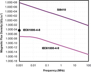
Such a field would most likely destroy surrounding circuitry before damaging the ISOpro isolation barrier circuit. In addition, ISOpro isolators have high electric field immunity (20 V/metre minimum) as measured by independent laboratories.
Application examples
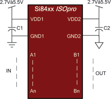
Unlike optocouplers, which need external components to improve performance, provide bias or limit current, the ISOpro isolators need only two external VDD bypass capacitors (0,22 to 1 μF) to operate. Their TTL level-compatible input terminals draw only microamps of leakage current, allowing them to be driven without external buffering circuits. The output terminals have a characteristic impedance of 50 Ω (rail-to-rail swing) and are available in both forward and reverse channel configurations. Note that the circuit of Figure 8 is typical for most applications and is as easy to use as a standard CMOS logic gate.
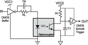
Figures 9, 10 and 11 show three different circuits recommended by optocoupler suppliers, each requiring additional external components when compared to the ISOpro isolators. Figure 9 shows an isolated CMOS logic application. Here, a CMOS input buffer provides the correct input logic levels while supplying drive current for the optocoupler LED. Resistor RL limits LED current, and peaking capacitor Cp accelerates LED turn-on and turn-off time to reduce propagation delay to roughly 300 ns. The output circuit consists of a CMOS Schmitt trigger, which improves rise and fall time and provides additional noise immunity and low output impedance.
The circuit of Figure 10 trades higher power consumption and reduced LED life for improved CMTI. Note that this circuit can be combined with that of Figure 9 to improve its CMTI as well, but it requires additional external components. Resistor R1 has a relatively low value and overdrives the LED for improved CMTI when Q1 is off. The LED is turned off when transistor Q1 is on, shunting current around the LED to ground. Note that the efficiency of this circuit is poor because roughly the same amount of current is drawn from VCC1 whether the LED is off or on.
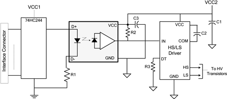
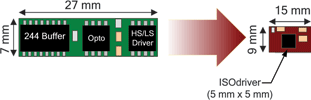
Figure 11 shows a high-voltage drive circuit for a plasma display. The incoming digital signal is conditioned by a logic buffer, which also provides drive current for the optocoupler LED. The optocoupler output drives a 600 V high-side/low-side driver, which, in turn, drives the high-voltage transistors that control the display.
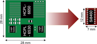
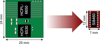
Figures 12, 13 and 14 show the impact of ISOpro isolators on the circuits of Figures 9-11. In all cases, the ISOpro isolator offers a substantial reduction in size and BOM while delivering better timing performance, lower power consumption and higher reliability than the optocoupler. The circuits in Figures 12 and 13 show the ISOpro isolator as a single-chip solution for the circuits shown in Figures 9 and 10. Figure 14 implements the circuit of Figure 11 using an ISOdriver, a device that combines RF isolation technology with a fully-featured, high-side/low-side IGBT/MOSFET driver capable of delivering up to 4 A peak.
For more information contact Gary de Klerk, NuVision Electronics, +27 (0)11 894 8214, [email protected], www.nuvisionelec.co.za
| Tel: | +27 11 608 0144 |
| Email: | [email protected] |
| www: | www.nuvisionelec.com |
| Articles: | More information and articles about NuVision Electronics |


© Technews Publishing (Pty) Ltd | All Rights Reserved
 printer friendly version