


The applications support team at Cree is often asked whether or not it is safe to operate its LEDs with pulsed currents above the maximum datasheet rating.
This question is usually asked in the context of legitimate product requirements such as those posed by emergency vehicle applications, specialised stroboscopic illumination and even pulsed modulation for general illumination dimming applications.
The short answer is ‘it depends’. Multiple variables affect both initial and long-term performance and reliability of an LED. These include thermal resistance, pulse duration, as well as current amplitude, frequency and duty cycle. In general, Cree’s XLamp LED product portfolio is sufficiently broad to accommodate the great majority of illumination and pulsed current illumination requirements within the datasheet specifications for these components. Products such as the XLamp XM-L have multi-ampere maximum current specifications[1].
However, to explore the limits of the possible, but not necessarily reasonable, this article will review three types of over-current conditions:
* Single-pulse events (eg, electrical overstress or EOS).
* Repetitive pulsing (eg, pulsewidth modulation).
* Ripple effects.
Electrical overstress (EOS) is often associated with catastrophic failures such as an electrostatic discharge (ESD), inrush current or other types of transient electrical surge[2]. Designers of LED drivers should be sure to take all necessary precautions to protect the LEDs from EOS.
The second type of over-current condition is often associated with applications where the LEDs operate in a flashing mode such as emergency vehicle lights, strobe lights or signalling beacons. High-frequency pulsing (ie, greater than 120 Hz) is often used to control the brightness of LEDs in dimming applications.
Finally, ripple current is a repetitive, cyclical peak-to-peak variation in a direct current waveform that may be derived from an insufficiently filtered alternating current source or switched mode power supply.
Within specification boundaries, none of these conditions is cause for concern in the long-term lumen maintenance or reliability of the LED. But any of these in an ‘over-current’ situation (that is, beyond datasheet specification) can decrease LED lifetime.
Single-pulse over-current events
Single-pulse over-current events are often the result of an unintentional application of excessive electrical energy to one or more LEDs and typically lead to a catastrophic failure of the device(s). Cree XLamp LEDs are capable of withstanding current transients that are several times higher than the maximum rated current.
However, the exact amplitude that a particular LED device can withstand is also a function of the duration and frequency of the transient. Beyond a certain threshold, a single-pulse event will lead to an immediate catastrophic failure of the LED. In this case, there are two general failure modes: either a short circuit or an open circuit.
The main factor limiting an LED’s ability to withstand an EOS event is the current carrying capability of the LED chip and internal interconnections. Current density is given as the electric current per cross-sectional area and is usually measured in amperes per meter squared (A/m²). Conventional electrical conductors have a finite resistance, causing them to dissipate power in the form of heat. Current (and therefore current density) must be kept sufficiently low to prevent the conductors from melting or fusing, or the insulating material from breaking down.
For example, at high current densities, material forming the interconnections can move. This phenomenon, known as electromigration, occurs when some of the momentum of moving electrons is transferred to nearby ions, causing them to dislocate from their original lattice positions. Electromigration does not occur in semiconductors directly, but in the metal interconnects deposited onto them. Over time, electromigration can transport a significant number of atoms far from their original positions and contributes to a device break down.
A localised increase of current density, known as current crowding, is an inhomogeneous distribution of current density through a conductor or semiconductor, especially at the vicinity of the contacts and over the p-n junctions. It is one of the known factors that limit the efficiency of LEDs and materials with low charge carrier mobility, such as indium gallium nitride (InGaN).
Current crowding can lead to localised overheating and formation of thermal hot spots, which in catastrophic cases can lead to thermal runaway and can also aggravate electromigration effects and formation of voids, causing localised, unevenly distributed current density. The increased resistance around a void is a self-feeding cycle, causing further localised temperature rise, which in turn accelerates the formation of the void and eventually can lead to an open-circuit failure.
Conversely, localised lowering of current density, with an implied current-density gradient, may lead to deposition of migrated atoms from current-crowded regions. In a similar self-propagating cycle, this can lead to further lowering of current density and further deposition of migrated ions, even the formation of small protuberances, which in turn can cause short circuits.
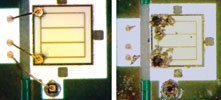
Figure 1 depicts two examples of metal migration. The picture on the left shows a device that has been subjected to repeated transient currents below the maximum threshold, while the one on the right shows a device subjected to roughly 20 times the normal forward voltage, resulting in a dramatic, instantaneous failure. These effects can always be mitigated with proper power supply design, which prevents electrical transients from reaching the LED component.
Another theoretically limiting factor is the current carrying capacity of the bond wire(s) to the LED chip. If this capacity is exceeded (as in a massive EOS), then the conductor(s) will fuse and cause an open circuit. While the exact physics involved in the fusing of a metal wire or conductive pad are beyond the scope of this article, the factors include the wire length and diameter, the type of bonds (ball or wedge) and physical material properties of the metal, including melting point, thermal conductivity, electrical resistivity, etc. Fusing of the bond wire is a highly uncommon, secondary failure that will occur only after the chip has already failed short and continues to be subjected to excessive current, which in turn leads to overheating of the bond wire(s).
Repetitive pulsing
The second type of over-current condition – high-current repetitive pulsing – may or may not result in an early catastrophic failure of the LED. Repetitive high-current pulsing may still result in a shortened life expectancy for the LED compared to the usual expected lifetimes on the order of tens or hundreds of thousands of hours.
A particular device could be subjected to repeated transients at an amplitude some percentage above the datasheet limits but below the threshold required for single-pulse failure, yet it will still eventually fail. The failure mechanism will be most likely due to electromigration as enough metal ions are eventually shifted away from their original lattice positions. The other factor that can lead to a reduced lifetime is excessive heating of the p-n junction, which causes the LED’s output to degrade below 70% of its original luminous flux.
Cree’s application engineering group tested four different types of XLamp LEDs over a broad range of pulsed currents, including levels well above the maximum rated continuous current. The data shows that above certain levels, there is little gain in light output and efficiency decreases. Thus, Cree does not recommend that customers operate LEDs at such extreme levels.
The charts in Figures 2 to 5 show the relationship between current amplitude and luminous efficiency typical of white XP-C, XP-E, XP-G and MX-6 LED devices operating at three different duty cycles (5%, 20% and 50%), at a frequency of 1000 Hz[3]. The dashed vertical lines represent the maximum rated continuous current for each XLamp LED product type.
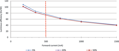
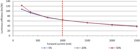
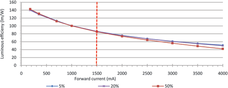
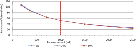
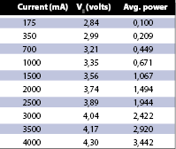
The relationship between light output and forward current is non-linear, as is the relationship between forward voltage and current. For example, increasing the drive current to the LED by a factor of two will result in an increase in power greater than a factor of two, as shown in Table 1 which is derived from the data in Figure 4. The same holds true for light output. Doubling the current will not double the output, and in fact, above a certain point, light output may even begin to decrease as the internal temperature of the LED rises.
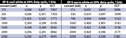
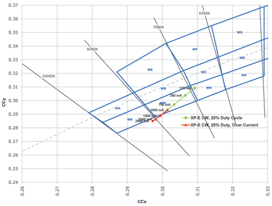
In addition to reduced efficiency, there are other potential problems caused by driving LEDs at high currents, including chromaticity shift. As the LED forward current increases, the x and y colour coordinates begin to shift to the left and downwards on the CIE 1931 colour space, resulting in an increase in correlated colour temperature (CCT). Table 2 shows data typical for a cool white and a warm white XP-E.
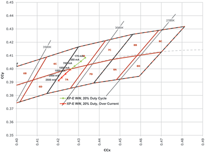
Figures 6 and 7 represent information from the same data set plotted in the CIE colour space, with the averaged results of five XP-E LEDs showing the chromaticity shift within the maximum specified driving current (the green data sets) and the continuing chromaticity shift when driven at over-current specifications (the red data sets).
An even greater long-term reliability concern is the effect of operating LEDs at elevated currents. This is due to heating of the p-n junction, especially for duty cycles greater than 25%. In order to determine if the maximum junction temperature (Tj) will be exceeded, one must measure the current (If), voltage (Vf) and case temperature (Tc) of the LED. For a pulsed LED, the power will be proportional to the duty cycle (D); therefore, to calculate Tj the following formula can be used: Tj = Tc + D * If * Vf * Rthj-c.
However, this is only part of the equation. The ambient temperature and thermal resistance from the case to the ambient air must also be factored in. Proper thermal management techniques must still be followed[4]. Based on the 1 kHz pulse testing reviewed in this article, Cree suggests the following guidelines for pulsed current operations:
* For duty cycles between 51% and 100%, do not exceed 100% of the maximum rated current.
* For duty cycles between 10% and 50%, do not exceed more than 200% of the maximum rated current.
* For duty cycles less than 10%, do not exceed more than 300% of the maximum rated current.
In addition to degradation in light output, other properties that may be affected over the long term by high-current operation are colour-point stability, reverse leakage current and forward voltage. Cree recommends that customers perform their own long-term testing to ensure the reliability of their design.
Ripple current
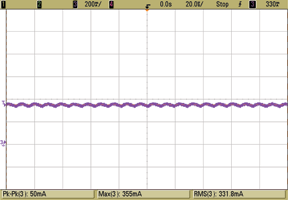
Ripple current is a periodic peak-to-peak variation in the current waveform (see Figures 8 and 9). Unfiltered, rectified 120 Hz signals are routinely used to drive LED illumination applications and, within specification boundaries, pose no problems whatsoever to the LEDs. However, excessive ripple current is something to be concerned about, and not just for the LEDs. It can also be a concern for electrolytic capacitors on the output filter stage of an LED driver. High ripple currents can lead to overheating of the capacitors and exacerbate early failure of the driver circuitry. There is also a chance that if the filter capacitors fail, transient currents that would otherwise have been attenuated will become present and may in turn cause damage to the LED.
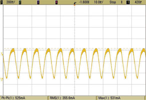
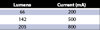
Large swings in peak-to-peak current may also affect the luminous efficiency of the LED. As an example, take a sample XP-E lamp with the luminous flux as given in Table 3. If the lamp is driven at a steady DC current of 500 mA, the output will be 142 lumens. On the other hand, if it is driven with a current that oscillates between a minimum of 200 mA and a maximum of 800 mA, then the light output will swing between 66 to 203 lumens. The mean lumen output is only 134,5, which is about 5% less than when the LED is driven with a steady DC current.
Maximum switching frequency
The maximum switching frequency for pulsing LEDs will be limited by the turn-on time of the device as well as the rise and fall time limits of the switching circuitry. The typical turn-on time for an XLamp device is on the order of 100 nanoseconds or less, which would limit the maximum switching frequency to approximately 10 MHz.
Summary
While Cree’s XLamp products are capable of withstanding current transients well above the maximum rated continuous current, there are physical limits that must not be exceeded in order to avoid EOS. It is possible to operate LEDs in a continuous pulsed mode at higher levels, but there will be trade-offs that may adversely affect efficiency, chromaticity and long-term reliability.
For certain specialised applications, there may be a good reason to exceed maximum current ratings to achieve a desired level of performance. However, for these cases, Cree recommends that customers perform their own life testing when proving out a design that will deliver any of the three over-current conditions described here.
Notes
1. As of December 2010, Cree has not performed significant over-driving tests on the XLamp XM-L LED.
2. See Cree application note CLD-AP29, ‘Cree XLamp LED Electrical Overstress’ (http://www.cree.com/products/pdf/XLamp_Elec_Overstress.pdf) for a discussion of recommended design practices to avoid EOS damage.
3. This information is presented for illustrative purposes only and is not intended to be used as a specification.
References
* Wire bonding in microelectronics: materials, processes, reliability and yield, George C. Harman, pp. 58-61.
* Advanced wire bond interconnection technology, Shankara K. Prasad pp. 25-26.
* ‘Physical Analysis of Data on Fused-Open Bond Wires’, Eugene Loh, IEEE Transactions on Components, Hybrids and Manufacturing Technology, Vol. CHMT-6, No. 2 June 1983.
* ‘Electrical Overstress in Integrated Circuits,’ J.T. May.
* Handbook of Nitride Semiconductors and Devices, Physics and Technology of GaN-Based Optical and Electronic Devices, Vol. 3, H. Morkoc.
* ‘Current spreading and thermal effects in blue LED dice’, K. A. Bulashevich, I. Yu. Evstratov, V.F. Mymrin, S. Yu. Karpov.
For more information contact Thami Moitoi, Arrow Altech Distribution, +27 (0)11 923 9600, [email protected], www.arrow.altech.co.za
| Tel: | +27 11 923 9600 |
| Email: | [email protected] |
| www: | www.altronarrow.com |
| Articles: | More information and articles about Altron Arrow |


© Technews Publishing (Pty) Ltd | All Rights Reserved
 printer friendly version