


The trend by power semiconductor manufacturers over the past years to increase the switching speed of their devices offers the benefit of reduced switching losses and the possibility to improve the efficiency of the system.
These power devices require optimised parasitic inductances (Lσ) of the DC link circuit. With an eye towards the needs of high-power applications with their larger currents in various setups, Infineon’s 650 V IGBT4 has been designed to provide an additional degree of freedom.
The device features an improved softness during switch-off and a lower overshoot voltage as the result of a reduced turn-off current slope di/dt. It was designed especially for medium- and high-current applications. In comparison with the 600 V IGBT3, the new chip offers a better softness during switch-off and higher blocking voltage capability. Moreover, the short circuit robustness is significantly improved. By contrast, the IGBT3 has been optimised for lower-power applications, or higher power in very low stray inductance applications.
Design and technology of the IGBT4
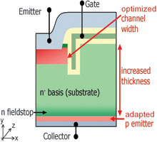
The IGBT4[1] utilises a trench MOS-top-cell, thin wafer technology and a field-stop concept as seen in Figure 1. The combination of trench cell and field-stop enables comparatively low on-state and turn-off losses. Compared to the IGBT3, the chip thickness was increased by about 15% and the width of the MOS channel was decreased by about 20%. Thereby, the softness during switch-off is improved to reduce the EMI effort. However, these measures obviously also cause additional losses. So in order to compensate for these side effects, the efficiency of the backside emitter was increased by 50%. In addition to the optimisation of the dynamic behaviour, the blocking voltage was increased by 50 V to 650 V.
Results of the IGBT4 dynamic characterisation
The stray inductance, in combination with the current gradient, has an influence on the voltage characteristic during turn on and turn off as ΔV=L*di/dt. Thus the over-voltage increases when switching off with larger Lσ. The turn off behaviour is quite insensitive to the gate resistance. This behaviour is well known for trench field-stop IGBTs[6]. A consequence of this inherent IGBT behaviour would be in such a case of a special driver stage with integrated IGBT protection functionalities and/or additional components like snubber capacitors. All these functionalities and components create design effort and cost. High current levels need, due to the high di/dt level, a DC link design with very small parasitic inductances. As an alternative, specially designed IGBTs with a soft switching characteristic like the IGBT4, can be utilised.
The difference between the fast 600 V IGBT3 and the soft 650 V IGBT4 in terms of switching behaviour becomes obvious by considering Figure 2, where the switch-off behaviour of high-current 600 A EconoDUAL3 modules are compared.
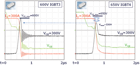
For the investigations, a standard DC link design with Lσ = 60 nH was used. This setup is not ideally suited for a high-current setup with the IGBT3[5]. Consequently, the switch-off of a current of 50% Inom, IC = 300 A, and a DC link voltage of 300 V at 25°C effects a fairly high overshoot voltage VCE,max and a snap-off with oscillations. In contrast, the IGBT4, especially designed for such high-current applications, shows a smooth switch-off with a much lower VCE,max, even at the typical DC link voltage of 300 V in specific high-current setup.
In the given test setup, the IGBT3 device reaches the limit of 600 V while the IGBT4 shows a smaller over-voltage of 530 V. In addition to the reduced over-voltage shoot, the increased blocking capability VCE,max offers the advantage of an increased safety margin during turn-off.
Not only the turn off characteristics, but also the softness of the IGBT is quite insensitive to the gate resistance. The softness during switch-off is improved to reduce the EMI effort. In Figure 3 the Fourier transformation spectra of a soft and a not soft turn-off waveform are given. The oscillation leads to a five times higher level around the oscillation frequency of roughly f = 20–25 MHz, a frequency which is quite typical for chip DC link oscillations at the given parasitic inductance.
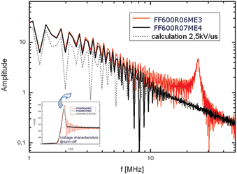
Even though such a procedure is not able to predict passing or failing of an EMI qualification, it obviously demonstrates the sensitivity of EMI to snap-off phenomena. The most important aspect in all designs is the improvement of the DC link design in order to be able to prevent additionally any kind of oscillations. For the inductance, ‘the lower the better’ is a simple rule for high-efficiency designs.
On the other hand, the softer switching behaviour has to be paid for with higher losses during switch-off, Eoff, and with a slightly increased saturation voltage ΔVCEsat ≈ 100 mV @ T = 25°C. Taking into account common switching frequencies, this increase does not play a major role. This fact is visualised in Figure 4 showing a simulation with IPOSIM.
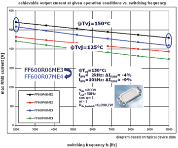
This tool, the Infineon Power Simulation program, can be found on the Infineon homepage (www.infineon.com). It performs a calculation of switching and conduction losses for all components, taking into account thermal ratings. As can be seen in Figure 4, the reduction of the RMS module current due to increased losses of the IGBT4 is only moderate, between 4 and 9% at switching frequencies of 2 kHz up to 10 kHz, a typical range for common applications.
Besides this standard operation, the design must be robust and also has to withstand a case of failure. The established value in power semiconductor datasheets is the specification of a hard short circuit current (ISC).
Short circuit robustness
Despite the considerably reduced silicon thickness of field-stop devices as compared to non-punch-through (NPT) designs, field-stop IGBTs are known to feature good short circuit robustness[3,4]. With the 650 V IGBT4, the short circuit robustness is significantly enhanced compared to the IGBT3. The increased thickness of the chip offers a larger thermal budget due to the thermal capacity of the silicon volume. In addition, the decreased channel width reduces the level of the short circuit current (this effect is shown vice versa in[5]).
In summarising, the IGBT4 can resist higher short circuit energy, and therefore the device is able to withstand a longer short circuit pulse time without being destroyed. In Figure 5, a typically hard short circuit pulse measurement of the IGBT4 is displayed. As the graph shows, the pulse time short circuit event was 10 μs, and the short circuit current typically is about four times the nominal current of the FF600R07ME4 device.
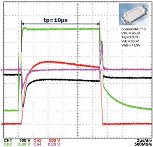
The device shows excellent switching and short circuit robustness with the specified short circuit time having been adjusted from 6 μs for the 600 V IGBT3 to 10 μs for the 650 V IGBT4.
References
[1] A. Härtl, M. Bässler, M. Knecht, P. Kanschat: ‘650 V IGBT4: The optimised device for large current modules with 10 μs short circuit withstand time’, Proc. PCIM Europe, (2010).
[2] H. Rüthing et al.: ‘600 V IGBT3: Trench field stop technology in 70 μm ultra thin wafer technology’, Proc. 15 th ISPSD, 66 (2003).
[3] M. Otsuki et al.: ‘Investigation on the short-circuit capability of 1200 V trench gate field-stop IGBTs’, Proc. 14th ISPSD, 281 (2002).
[4] T. Laska et. al.: ‘Short circuit properties of trench-/field-stop-IGBTs – Design aspects for a superior robustness’, Proc. 15th ISPSD, 152 (2003).
[5] P. Kanschat, H. Rüthing, F. Umbach, F. Hille: ‘600 V IGBT3: A detailed analysis of outstanding static and dynamic properties’, Proc. PCIM Europe, 436 (2004).
[6] W. Rusche: Infineon Application Note ‘AN2003-03, Switching behaviour and optimal driving of IGBT3 modules’ (2003)
For more information contact Davis Moodley, Infineon, +27 (0)11 706 6099, www.infineon.com


© Technews Publishing (Pty) Ltd | All Rights Reserved
 printer friendly version