The combination of digital media, personal computing and global networking is creating a radical shift in the telecom industry. The key trend is towards IP-fixed/mobile network convergence for the delivery of voice, video and data applications with IP (and Ethernet) as a common universal platform fuelled by the exponential growth of video, gaming, collaboration and cloud computing applications. This trend significantly stresses the transport backbones, which have been built on 10G wavelengths, and is driving the need for upgrades to 40G and 100G.
The IEEE 802.3ba standard defines a single architecture capable of supporting both 40G and 100G Ethernet, while producing physical layer specifications across backplanes, copper cabling, multimode fibre and single-mode fibre. The new 40G/100G Ethernet architecture is based on the concept of virtual lanes or physical coding sublayer (PCS) lanes, which would get multiplexed and transported over the four or 10 parallel wavelengths on a single fibre. For example, 100GBASE-LR4 has four optical wavelengths of 25G on the fibre coming from 10 electrical CAUI signals of the Gbps on the host side.
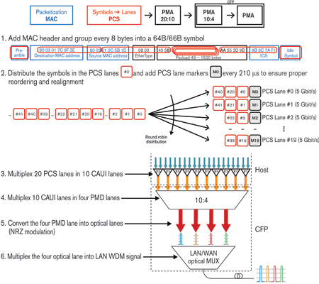
In the process of transmitting a 40G/100G Ethernet signal (as illustrated in the figure), the Ethernet packet is broken into blocks, which are then mapped into PCS lanes using a round robin distribution. To ensure a clean realignment of the entire block and to manage the skew between blocks at the receive side, a marker block is added on each logical lane. This marker is sent at a fixed cycle of 210 μs.

The 20 PCS logical lanes will then be multiplexed down to 10 lanes at 10 Gbps, also called CAUI lanes, using the physical medium attachment (PMA) located in the CFP optical interface. The unique property of the PCS lanes is that no matter how they are multiplexed together, all bits from the same PCS lane follow the same physical path; this enables the receiver to correctly reassemble the aggregate channel. At the same time, the unique lane marker enables the deskew operation in the receiver.
The 40G/100G Ethernet implementation introduces new challenges at the electrical and optical layers. These challenges are due to the data distribution over multiple channels, combined with the skew effect. This triggers the need to test individual concepts, such as PCS lanes, PCS skew and the alignment markers, to ensure that the 40G/100G Ethernet device under test (DUT) supports the proper realignment capabilities, thus compensating for physical characteristics of the link. By inserting multiple UI of skew on different lanes, engineers can identify receiver buffer issues, which is crucial when validating the skew tolerance of the 100G system.
Since many of the initial deployments of 100G Ethernet address bandwidth needs at the core, optical transport networks (OTNs) for transport applications become prevalent. The newly defined OTU4 (112 Gbps) rate in ITU-T G.709 addresses the need for carrying 100G Ethernet services over OTN. This is in addition to the fundamental benefits of OTN in general, such as supporting operations, administration and maintenance (OA&M) procedures, as well as providing a standardised forward error correction (FEC) mechanism for enhanced network performance and better deployment economics.
Similar to those defined by IEEE P802.3ba, ITU T SG 15 had defined a new layer on top of the optical channel transport unit (OTU), which is known as the ‘optical channel transport lane’ (OTL) protocol. The OTL layer is defined as OTL x.y, where x is the data rate and y is the number of optical lanes. For example, OTL 4.4 represents an OTU4 signal running on four wavelengths at 28G.
OTL introduces elements such as OTL lanes, OTL skew and OTL alignment markers, which are conceptually similar to the PCS lanes, PCS skew and the PCS alignment marker described in IEEE P802.3ba. As with Ethernet, the OTL layer uses the logical lane markers to realign all the sent blocks. The main differences in this case are that the marker is embedded in the frame alignment signal (FAS) and the multiframe alignment signal (MFAS) Bytes of the OTN frame. Therefore, when validating 100G devices supporting OTN capabilities, it is crucial to test the skew at the OTL layer, in addition to testing all other OTN layers, including OTU4, ODU4, OPU4 and FEC to ensure the proper mapping and de-mapping of 100G Ethernet client signal and reporting of fault management.
Qualifying the performance of the OTN physical layer by testing the line rate of the signal with a pseudo random bit sequence (PRBS) pattern is a key step. This test is critical for designers and system engineers during the development of the 100G line cards. One of the main tests is to inject a complex PRBS pattern onto each of the physical lanes and analyse the bit error rate (BER) at the receiver end. The power to inject different patterns per lane provides a complete overview of the crosstalk between the channels as well as a maximum density pattern, which can be configured to verify the receiver PLL response to unbalanced bit density.
EXFO’s FTB-851100G Packet Blazer 100G/40G Ethernet test module offers a wide range of 40G/100G testing capabilities for the physical layer with its signal conditioning interface designed to qualify CFPs to IP testing at 40G/100G line rates and Ethernet mapping into OTN. These tests are critical from network equipment manufacturers’ perspective during the development, design and validation stages.
For more information contact Chris Nel, Lambda Test Equipment, +27 (0)12 349 1341, [email protected], www.lambdatest.co.za
| Tel: | +27 12 349 1341 |
| Email: | [email protected], [email protected] |
| www: | www.lambdatest.co.za |
| Articles: | More information and articles about Lambda Test |

© Technews Publishing (Pty) Ltd | All Rights Reserved