


The majority of commercially available precision timing and frequency generation standards provide very accurate signals at a fixed RF frequency (typically 10 MHz) coupled with a precision timing pulse, usually at the rate of 1 pulse per second, generated from a divided down version of the RF signal.
In many applications, the user wishes to generate a non-standard RF or pulse frequency without sacrificing precision. This article describes an implementation that enables a user to generate any required frequency to a resolution of 0,1 Hz over a frequency range of 0 to 30 MHz, and by using this capability and a precision timing signal, generate small phase shifts to a resolution of 1 ns.
Background
For a number of years, direct digital synthesisers (DDS) have been available, primarily for use in applications such as secure radio communications, frequency hopping, etc. With the popularity of these devices, the performance has been improved to a point where now it is possible to obtain 48-bit devices, ie, that provide a resolution of 248.
Utilising this capability a unique test was developed to measure the frequency accuracy and stability of precision time and frequency devices. This capability was then expanded to create an instrument with the capability of providing not only multiple settable output frequencies locked to a precision source, but to also generate very small (nanosecond range) phase shifts on an RF signal.
Implementation
Frequency generation
The basic frequency generation system is fairly straightforward. An incoming precision frequency reference (10 MHz) is used to drive a phase locked loop generating a 100 MHz RF signal to be used as a system clock. This system clock is used as the clocking input to a 48-bit DDS which is programmed with the necessary frequency tuning word by means of an embedded processor to provide the desired output frequency.
To simplify operation, the calculation to produce the necessary frequency is handled by the processor once the desired frequency is entered. The calculation is:
Frequency tuning word = Desired output frequency x 248/SYSCLK
The DDS used includes two separate frequency tuning word registers (FTW1 and FTW2) and for generation of a simple single-frequency output, FTW1 is used.
Phase offsets
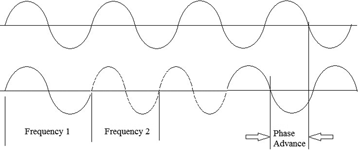
In order to produce a phase continuous phase offset on an RF frequency, the dual frequency register features of a DDS become particularly interesting. Conceptually, a phase change implementation can be pictured as a small frequency change for a finite amount of time as shown in Figure 1.
The calculation for the required frequency change over a given period of time is derived from:
dt/T = dF/F
or
dF = dt x F/T
where: dt is the phase change desired
T is the period for which the changed frequency will be applied
dF is the change in frequency required to achieve the phase change
F is the original output frequency
As an example, if we wish to shift the output phase of a 10 MHz output sine wave by 1 nanosecond, then with a gating time of 0,1 seconds the change in frequency is :
dt = 1 nanosecond = 1 x 10⁻⁹ seconds
F = 10 MHz = 10 x 106 Hz
T = 0,1 seconds
dF = 1x10-9 x 10 x 106 /0,1 = 0,1 Hz
This is the change in frequency. Therefore if we apply a frequency of 10 MHz + 0,1 Hz, or 10 000 000,1 Hz for 0,1 seconds, we will achieve a phase advance of 1 nanosecond. Similarly if we apply a frequency of 10 MHz–0,1 Hz for a period of 0,1 seconds we will achieve a phase retardation of 1 nanosecond.
This technique is implemented by preloading the second frequency tuning word (FTW2) with the necessary frequency, and then gating FTW2 for a very precise period. Gating times down to 10 ns can be generated very accurately from the system clock, which in turn is locked to the incoming precision reference, and so very accurate phase changes can be achieved.
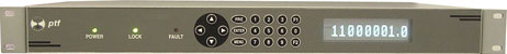
The above capabilities have been realised in the ptf 1229A from Precise Time and Frequency. The instrument allows both precision frequency setting and precision phase setting from both local keypad controls and remotely via either telnet or RS232 monitor/control capabilities.
| Tel: | +27 11 782 8728 |
| Email: | [email protected] |
| www: | www.accutronics.co.za |
| Articles: | More information and articles about Accutronics |


© Technews Publishing (Pty) Ltd | All Rights Reserved
 printer friendly version