


Among all product characteristics relevant when selecting or integrating the appropriate connector into equipment, voltage ratings are often of crucial importance because they are safety related. Unlike most product specifications, operating voltage is not an intrinsic characteristic of a connector because this voltage is also affected by the environmental conditions such as humidity and air pressure, as well as safety requirements that are often field specific.
This article provides guidelines to help equipment manufacturers choose the adequate product and operating conditions. The first step however is to identify if specific regulations or standards exist for the equipment being designed, as they must be considered as a priority.
Definitions
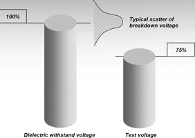
Dielectric withstand voltage is the breakdown value of the component in a destructive test.
Test voltage is the voltage level at which the connector is tested during qualification testing. According to IEC 60512-2, the test shall last 1 minute and no flashover or breakdown is allowed.
This value represents the upper physical limit and is sometimes used as a basis to calculate operating levels when predefined safety factors are established.
In theory, test voltage may be as high as possible provided the conditions of the standard are met. Practically, however, the test voltage is usually set at 75% of dielectric withstand value (as defined for example in MIL-STD-1344). Fischer Connectors always applies this ratio; the resulting test voltage values are therefore reliable even when breakdown values exhibit the large scatter typical in high-voltage testing (see Figure 1).
Operating voltage is the voltage under which the connector will actually work in the equipment over the normal expected lifetime and in typical environmental conditions. As we will see, this value depends both on connector design and on the specific operating environment.
Significant scatter is often observed in breakdown testing because the breakdown mechanism is naturally triggered by instabilities. Withstand voltages determined at various locations with different equipment frequently result in up to 10% differences. Such scattering is not evidence of differences between the test samples.
The overall performance of any electrical connector is typically determined by the spacing of the contacts (air gap), the distance along insulating components (creepage distance) and of course by the choice of the insulating material. In most general-purpose connector designs the short term performance is driven by the insulating performance of the surrounding air, whereas in the long term the physical properties of the insulating material are important.
Determination of operating voltage
The operating voltage, as defined here, must be applicable to the device over the entire lifetime of the equipment and under typical working conditions. This means that one also has to take into account a possible long term degradation of the insulating materials under aggressive environmental influences. This is typical for all kinds of electrical devices and has led to the development of generic standards providing adequate guidelines.
In particular, IEC60664 is recommended. This specification uses creepage distance instead of test voltage as the calculation basis for the operating voltage, taking into account the aforementioned long-term effects. It is similar to German VDE 0110, where typical applications are classified in insulation groups depending on their exposure to pollution.
Fischer Connectors recommends the use of IEC60664 in the general multipole connector specifications, unless other more specific standards or regulations are applicable to the design. For example, IEC 60601 provides adequate special guidelines for medical devices.
All values given herein are valid for mated connectors and provided that termination of connectors has been done with adequate cable and following correct termination procedures.
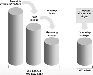
Other previous standards recommend a calculation using the test voltage as the basis, with the application of a safety factor. For example, former IEC 60130-1 recommends setting the operating voltage at:
0,33 x test voltage for 500 V < test voltage < 3 kV
0,66 x test voltage for test voltage ≥ 3 kV
Similar recommendations are provided in MIL-STD-1344 method 3001.
This method takes into account the measured test voltage of the connector, however it does not take into consideration long term environmental effects, nor the specific behaviour of different insulator materials. This method can be recommended for cases where the connector ‘on time’ or duty cycle is low, combined with little exposure to environmental factors, for example scientific instruments or similar equipment. Fischer Connectors provides test voltage values in the general catalogue and in some product specifications.
Figure 2 shows a comparison of both design methods. No precise rule can be given for the selection of the best method to determine operating voltage. Thorough study of the specific application, the operating conditions and relevant safety rules, is essential for the designer.
Frequency effects
Both methods described above are valid for conventional DC or low-frequency AC conditions. At high frequencies, additional physical effects in the insulating material may significantly affect the performance of the connector.
At low frequencies, electrical charges on the insulator surface will move according to their relative freedom of movement; time within a cycle is sufficient to relax the local accumulated charges. At high frequencies (typically above the kHz range), the simultaneous displacement of these charges leads to the well known corona effect or partial discharge, accelerating the breakdown.
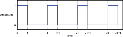
Particularly critical are high-frequency pulsed signals as they exhibit very high du/dt values.
No specific guidelines can be given to adapt operating voltage to these conditions, which require individual testing. But as a rule of thumb, based on IEC 60664 data, one can estimate that a derating down to 50% may be needed at critical kHz frequencies. Of course the connector cannot be considered as an isolated element; in such critical situations the response of the entire system including cables and other devices should be evaluated.
Effect of air pressure
The insulation properties of all gases, including air, are strongly influenced by their pressure. This pressure directly determines the density of the gas and therefore the actual breakdown voltage. Connectors and other similar devices using air as insulator must be designed to take this fact into account. Furthermore, correction factors must also be applied to the connector’s normal voltage rating for those applications in which the connector is expected to operate at non-standard atmospheric pressure.
Basically, the breakdown voltage of a connector in a gas will decrease as the pressure decreases. This phenomenon is called Paschen’s law and the curves are of empirical origin – see Figure 4.
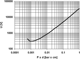
Specialised high-voltage literature can provide more details and data for specific gases.
Use of a connector in a vacuum application
Paschen’s law is essential in vacuum applications; graphs can assist in determining the correct parameters of the connector’s operation, but thorough testing is essential. It is also recommended that power is switched off during the degassing phase of vacuum equipment to avoid exposure of the connector to the most critical low insulating atmosphere.
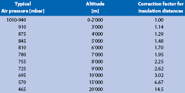
Use of a connector at high altitude
Generally, the physical phenomena influencing breakdown voltage at elevated altitudes are similar to those in a partial vacuum. However, special attention should be paid to the fact that specific atmospheric parameters like temperature and moisture, which also affect dielectric behaviour, are of an uncontrolled nature.
Limitations
The formulas and values presented in this article are given only with the intention of assisting with the choice of a connector with respect to its particular application. It remains always the responsibility of the equipment manufacturer, and not the connector supplier, to determine the appropriate technical standards as well as the necessary safety factors for a given application.


© Technews Publishing (Pty) Ltd | All Rights Reserved
 printer friendly version