


Making good spectrum and vector signal measurements such as demodulation gets tougher as frequencies get higher, and there are special challenges at millimetre frequencies and beyond. This article discusses the choice of measurement tools and will describe techniques to help make accurate and cost-effective measurements in different application environments.
Choosing the location of the first mixer
In signal analysers, one of the first elements in the signal path is a mixer used as a frequency translating device. For microwave and millimetre analysis, this mixer is the first step in several stages of converting the signal to a range where it can be measured, typically the final intermediate frequency (IF) stage. This mixer is very close to the input connector because signal path loss increases rapidly with frequency, and sensitivity is optimised when the signal is down-converted as early as possible.
This ‘first mixer’ need not be inside the signal analyser in all cases. To optimise measurement performance, solution cost and operational convenience, one can consider alternatives in light of recent developments in analysers, mixers and ultra-wide bandwidth signal sampling technology.
The fundamental mixer choice
Most choices related to signal connection and mixing can be boiled down to three categories: internal mixing, external mixing and ‘no mixer’. Each of these is worth a closer look.
Internal mixing
This is the default choice, especially for microwave (as opposed to millimetre) measurements. The first mixer is inside, and very near the input connector of the analyser, often preceded by an attenuator and sometimes a preamplifier. This is a single-box, single-connection approach that typically uses a coaxial connection.
The analyser handles all operations including down-conversion, digitising, analysis and display. For microwave and millimetre measurements, some form of harmonic mixing is used inside the analyser, and in many analysers a bandpass ‘preselector’ filter (inside the analyser) is tuned to the frequency of the signal/system under test (SUT) to avoid the production or display of unintended mixing products.
External mixing
This method typically takes one of two forms, either standalone external mixers or separate down-conversion assemblies. As the name implies, the first mixer is external to the analyser and typically does not include an attenuator, preamplifier or preselector (some preselected external mixers are available). Instead, the analyser supplies a microwave local oscillator (LO) signal to the external mixer and receives an intermediate frequency (IF) signal from the mixer. This IF signal is the result of mixing the SUT with harmonics of the LO signal supplied by the analyser.
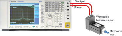
The external mixer is often attached directly to the SUT using a waveguide or coaxial connection. The analyser further processes the IF signal with filtering, digitising, analysis and display operations similar to those for internally-mixed signals.
No mixer
The advent of oscilloscopes with analog bandwidths that extend to microwave and millimetre frequencies has widened the solution landscape. When paired with signal analysis software (typically vector signal analysis or VSA software) oscilloscopes can handle traditional signal analysis tasks such as spectrum analysis, temporal analysis and demodulation or modulation-quality analysis.
With a microwave or millimetre oscilloscope, the SUT is digitised directly and the sampled signal represents the entire frequency range rather than a narrower band of frequencies in the vicinity of the signal of interest. Though this may be characterised as a ‘no mixer’ approach, many signal measurements still involve band-selective analysis, with the VSA software performing the down-conversion (mixing), filtering and data reduction operations that would otherwise be handled by analog hardware.
Potential benefits of external mixing
Cost
Analyser price generally increases with frequency range, and microwave or millimetre frequency coverage may only be needed for a specific band or bands. External mixing can allow an analyser otherwise limited to RF or low microwave coverage to analyse signals at any frequency, using the appropriate external mixer.
Convenience and sensitivity
Some signals are provided through waveguide, which has comparatively low transmission loss but with connections that are typically inflexible and expensive. External mixing can allow the first mixer to be bolted directly to the waveguide supplying the SUT, with the analyser connections then accomplished by flexible, inexpensive, (comparatively) low-frequency, low-loss cabling.
Frequency coverage
Some frequency ranges are only covered by externally mixed solutions. Some signals cannot be readily connected to single-box solutions because of a combination of distance, physical configuration and loss in transmission.
Performance
Direct connection of the mixer to the SUT can improve the noise figure of the measurement system, improving both signal-to-noise-ratio (SNR) and accuracy. Phase noise performance may also be improved, due to higher LO output frequencies from modern analysers and the resulting lower harmonic numbers used by the external mixers. In some cases, externally mixed measurements can have significantly lower phase noise than one-box solutions.
Smarter mixers function as a ‘remote test head’
External mixer connections are relatively simple, requiring just one or two relatively low-frequency (10 GHz) cables for the interface with a spectrum or signal analyser. Accurate measurements require the analyser to be configured for the correct output frequency (mixer harmonic number) and associated mixer conversion loss.
Mixer conversion loss is accounted for through frequency response curves supplied by the mixer manufacturer and entered as amplitude correction factors in the analyser. These amplitude correction factors can be entered manually or uploaded from a disk or USB device. Configuring the analyser for a specific mixer introduces opportunities for error: in the entry of conversion loss numbers; the association of those numbers with a specific mixer; and in connection problems such as inadequate or unflat LO drive levels.
A simple digital interface between the host analyser and an enhanced or ‘smarter’ mixer can solve all these problems at once. For example, Agilent’s new M1970V/W waveguide harmonic mixers (Figure 2) store factory measured conversion loss parameters internally, along with model and serial number.
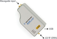
These mixers also contain an LO power measurement/monitor circuit to help optimise LO drive level across their frequency range and detect any connection problems.
Instruments such as the Agilent N9030A PXA signal analyser can then automatically detect these mixers through a simple USB cable, then download conversion loss information, configure themselves correctly for the specific mixer and perform an LO drive level alignment for optimum accuracy. The result is enhanced performance and measurement convenience, reduced chance of errors, and the implementation of a simple ‘remote measurement head’ that can be placed in the optimum configuration to the SUT.
Microwave? Millimetre frequencies? Terahertz?
Definitions vary but most consider microwave frequencies to cover 3 to 30 GHz while ‘millimetre frequencies’ or extremely high frequencies (EHF) refers to 30 to 300 GHz. Frequencies above 300 GHz are often called terahertz radiation.
This article will be continued in the next edition of Dataweek.
| Tel: | +27 12 678 9200 |
| Email: | [email protected] |
| www: | www.concilium.co.za |
| Articles: | More information and articles about Concilium Technologies |


© Technews Publishing (Pty) Ltd | All Rights Reserved
 printer friendly version