


In any electrical installation, some current will flow through the protective ground conductor to ground. This is usually called leakage current. Leakage current most commonly flows in the insulation surrounding conductors and in the filters protecting electronic equipment around the home or office.
So what is the problem? On circuits protected by RCDs (residual current devices), leakage current can cause unnecessary and intermittent tripping. In extreme cases, it can cause a rise in voltage on accessible conductive parts.
The causes of leakage current
Insulation has both electrical resistance and capacitance, and it conducts current through both paths. Given the high resistance of insulation, very little current should actually leak. But, if the insulation is old or damaged, the resistance is lower and substantial current may flow. Additionally, longer conductors have a higher capacitance, causing more leakage current.
Electronic equipment, meanwhile, contains filters designed to protect against voltage surges and other disruptions. These filters typically have capacitors on the input, which adds to the overall capacitance of the wiring system and the overall level of leakage current.
Minimising the effects of leakage current
So, how can you eliminate or minimise the effects of leakage current? Quantify the leakage current and then identify the source. One way of going about this is to use a leakage current clamp meter. These are very much like the clamp meters used for measuring load currents, but deliver significantly better performance when measuring currents below 5 mA. Most clamp meters simply will not register such low currents.
Once you place the jaws of a clamp meter around a conductor, the value of current it reads depends on the strength of the alternating electromagnetic field surrounding the conductors. To accurately measure low current levels, it is essential that the mating faces of the jaws are protected from damage, are kept clean and are closed completely together without an air gap when testing. Avoid twisting the jaws of the clamp meter as this can cause erroneous measurements.
The clamp meter detects the magnetic field surrounding conductors such as a single core cable, a wire armour cable, a water pipe, etc; or the paired phase and neutral conductors of a single-phase circuit; or all live conductors (3-wire or 4-wire) of a three-phase circuit (like an RCD).
When testing the grouped live conductors of a circuit, the magnetic fields produced by the load currents cancel each other out. Any imbalance current comes from leakage from the conductors to ground or elsewhere. To measure this current, a leakage clamp meter should be able to read less than 0,1 mA.
For example, taking a measurement on a 230 V a.c. circuit, with all loads disconnected, might result in a value of 0,02 mA (20 μA) leakage. This value represents an insulation impedance of 230 V/(20 x 10-6) = 11,5 MΩ.
If you conducted an insulation test on a circuit that was powered down, the result would be in the region of 50 MΩ or more. This is because the insulation tester uses a DC voltage for testing, which does not take the capacitive effect into consideration. The insulation impedance value is the actual value that exists under normal operating conditions.
If you measured the same circuit loaded with office equipment (PCs, monitors, copiers, etc), the result would be significantly different due to the capacitance of the input filters on these devices. When many pieces of equipment are operating on a circuit, the effect will be cumulative; that is, the leakage current will be higher and could well be in the order of milliamps.
Adding new pieces of equipment to a circuit protected by a RCD could trip the RCD. And because the amount of leakage current varies depending on how the equipment is operating, the RCD may trip randomly. Such intermittent problems can be difficult to diagnose.
A clamp meter will detect and measure a wide range of alternating or changing currents passing through a conductor under test. When telecommunications equipment is present, the value of leakage indicated by a clamp meter may be considerably more than that resulting from insulation impedance at 50 Hz. This is because telecommunications equipment typically incorporates filters that produce functional grounding currents and other equipment that produces harmonics, etc.
You can only measure the characteristic leakage at 50 Hz by using a clamp meter that incorporates a narrow band-pass filter for removing currents at other frequencies.
Measurement of leakage current to ground
When the load is connected (switched on), the leakage current measured includes leakage in load equipment. If the leakage is acceptably low with the load connected, then circuit wiring leakage is even lower. If circuit wiring leakage alone is required, disconnect (switch off) the load.
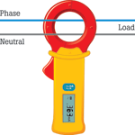
Test single-phase circuits by clamping the phase and neutral conductor. The measured value will be any current flowing to ground (see Figure 1).
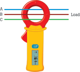
Test three-phase circuits by clamping around all three-phase conductors. If a neutral is present, it should be clamped along with the phase conductors. The measured value will be any current flowing to ground (see Figure 2).
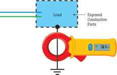
Measuring leakage current through the ground conductor
To measure the total leakage flowing to the intended ground connection, place the clamp around the ground conductor (see Figure 3).
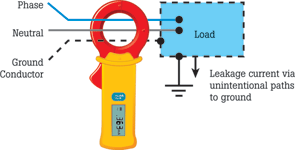
Measuring leakage current to ground via unintentional paths to ground
Clamping phase/neutral/ground together identifies imbalance current that represents leakage at an outlet or electrical panel via unintentional paths to ground (such as the panel sitting on a concrete base). If other electrical bonding connections exist (such as a connection to a water pipe), a similar imbalance may result (see Figure 4).
Tracing the source of leakage current
The series of measurements shown in Figure 5 identifies the overall leakage and the source. The first measurement can be made on the main conductor to the panel. Measurements 2, 3, 4 and 5 are made subsequently to identify circuits carrying the larger amounts of leakage current.

Summary
Leakage current can be an indicator of the effectiveness of insulation on conductors. High levels of leakage current may be present in circuits where electronic equipment with filters is used, and can cause voltages that disrupt normal operation of equipment. It is possible to locate the source of leakage current by using a low-current leakage current clamp to take methodical measurements as described above. If necessary, this enables you to redistribute loads around the installation in a more balanced way.
For more information contact Comtest, +27 (0)11 608 8520, [email protected], www.comtest.co.za
| Tel: | +27 10 595 1821 |
| Email: | [email protected] |
| www: | www.comtest.co.za |
| Articles: | More information and articles about Comtest |


© Technews Publishing (Pty) Ltd | All Rights Reserved
 printer friendly version