


Power supplies in complex electronic products and systems have evolved very rapidly over a relatively short period of years. Computer systems, and many other systems built around latest-generation microprocessors, digital signal processors and other complex chips fabricated in leading-edge technology, share a number of characteristics.
High up on that list, from the power system architect’s point of view, is the continuing trend to ever lower voltage rails that carry correspondingly high currents to power densely packed cards or processing blades.
Traditional power distribution architectures, in which centrally regulated bulk supplies were bussed around a system at the same voltage as they were consumed, were abandoned generations ago. Sharing currents of tens, and then hundreds, of Amps from a single source quickly became impractical. Not least among the problems was that, with the smallest IR drop in the wiring being a high proportion of the load voltage, precision regulation became all but impossible.
At the same time as sub-micron process technology was dictating the shift from 5 V to 3,3 V, then 1,8 V and so on down, power transistor progress (among numerous other trends) enabled the construction of compact and efficient switch-mode DC/DC converters or ‘bricks’. This in turn launched a progression in power distribution architectures that routed power around the system at (initially) a relatively high DC level of 48 V and converted it locally to the load voltage.
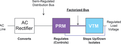
Vicor introduced converters for, in turn, distributed bus architecture, intermediate bus architecture and, currently, factorised power architecture (FPA). These have been well documented in Dataweek previously and will not be explored here, except to note that in FPA there is a fundamental reassignment of the locus of several key functions, compared to earlier schemes, that is essential to understanding the role of one of the most efficient DC/DC conversion schemes yet devised: sine amplitude conversion, or SAC.
In an FPA power distribution scheme (Figure 1), the function of regulation – maintaining a stable voltage in the presence of load and supply variations – takes place at the intermediate voltage level. The functions of isolation and conversion to the final desired load voltage, are combined in a novel circuit block termed the voltage transformation module or VTM. This function can also be described as a current multiplier, as its key feature is that it acts (allowing for inexact use of the terminology) as a ‘DC/DC transformer’. That is, it converts from DC to DC, with a fixed ratio.
In parallel with the evolution of power distribution schemes – and enabling that development – DC/DC converters also followed a path of increasing efficiency and power density. Early designs ‘hard-switched’ DC into an alternating square wave that was applied to the primary of a transformer. The resulting secondary voltage was rectified to yield the required output. Unsurprisingly, the presence of fast, high-current switched waveform edges gave rise to significant harmonic components that had to be filtered; and there were considerable losses, both conduction and switching, in the power devices.
These limitations began to be addressed by the use of a conversion circuit arrangement that contrived to turn power switches off and on at the point in the waveform where both current and voltage were at a zero crossing (Figure 2). A resonant tank circuit (comprising the added capacitor and the transformer
winding) on the primary provides the context for the quasi-sinusoidal waveform.
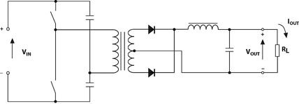
Switching losses were reduced; contemporaneously, improved transistors cut conduction losses. The primary waveform approximated to sinusoidal, and harmonic generation diminished. An important point in this circuit’s operation is that one cycle of the primary provides one ‘unit’ or ‘quantum’ of energy to couple to the secondary. If this converter is to respond to an increase in secondary load, the control loop must react by increasing the switching rate at the primary; the principal regulatory mechanism is via switching frequency.
The next architecture in the progression is SAC. It is important to note that SAC also employs ZVS/ZCS – in that its power switches turn off and on in near-ideal conditions – but that its operation is fundamentally different. The conceptual circuit arrangement is shown in Figure 3.
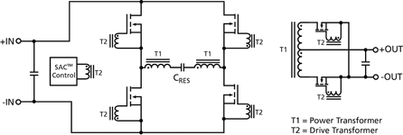
At the heart of the power path is the power transformer T1. A sinusoidal – fully-sinusoidal, in this case – waveform is excited in the primary, the resonant elements being the leakage inductance of the transformer and the inter-winding capacitor. The multiwinding transformer T2 is a control/drive component that provides the signals to the primary power switches, and to the synchronous rectifiers on the secondary side, to switch at the appropriate zero crossing points of the waveform.
That waveform, as noted above, is fully sinusoidal, continuously oscillating and of fixed frequency. Response to load changes is by a completely different mechanism to the previous case; here, a load increase prompts an increase in amplitude in the primary waveform, driving more energy to the secondary and maintaining the fixed conversion ratio from input to output.
The analogy with an AC transformer is useful (as long as the limitations of the analogy in understanding circuit operation are kept in mind); the V x A product at input and output is identical, allowing for losses. Those losses are very small – use of the latest semiconductors keeps conduction losses to a minimum, and as already noted, all switching is at zero crossing points. Conversion efficiency of
98–99% is achieved, contributing to very high power density and reduced thermal management requirements. With sinusoidal waveforms and negligible switching transients, harmonic content – both radiated and conducted – is also minimal.
Naturally, there are many subtleties to the detail design that are not apparent from the outline circuit of Figure 3. The designer must, for example, generate correctly shaped drive waveforms for each of the power switches from the waveforms coupled by the drive transformer; the designer must also ensure (again, taking just one example) that the converter starts under all load conditions.
In common with other devices in the most advanced power conversion families, the properties of every component – both primary and parasitic effects – are modelled, understood and fully exploited as an integral part of the design.


© Technews Publishing (Pty) Ltd | All Rights Reserved
 printer friendly version