


High oil and gas prices, climatic protocols and commitments from different national governments to decrease their CO2 emissions are among the factors driving the increase in sustainable energy generation installations, including solar energy.
To support these commitments, governments have introduced incentives such as preferential purchase prices for the captured energy fed into national grids, and capital subsidies for solar installations. Today’s electronic technologies also make a significant contribution to efficiency, making this energy source more profitable, which has led to a dramatic upswing in installed generating capacity.
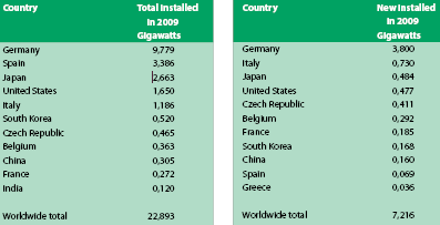
In 2009, an estimated 10,7 GW of solar photovoltaic (PV) cells were produced. As a reference, only 1 GW was produced in 2004. By the end of 2009, a total PV capacity of about 23 GW had been installed worldwide, with around 100 countries now using solar PV as a source of electricity. Germany is the worldwide leader in solar installations, with 3,8 GW installed in 2009 alone, amounting to over half of the estimated 7,2 GW added worldwide in that year; in 2009 Germany’s total PV capacity amounted to 9,8 GW. A further 3,8 GW was added in the first six months of 2010 alone.
The pioneering position on PV adopted by Germany is now being emulated by many countries worldwide, as Table 1 illustrates. For example, every two years, the USA is doubling the capacity of PV connected to the grid, the largest proportion being in California, followed by Florida.
As with any manufactured product, economies of scale apply and as production volumes increase, prices for the PV systems are decreasing, in turn further raising interest in PV on the part of investors. However, the same trend may also lead to renegotiation of some of the initial preferential purchase prices for the kWh to lower prices.
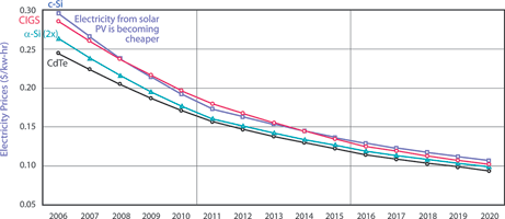
In 2010, the cost to produce electricity from PV was in the range 0,16 to 0,20 $/ kWh (see Figure 1), as compared to 0,10-0,15 $/kWh for fuel cell and 0,04 to 0,07 $/kWh for a wind turbine. For comparison, electricity from coal fired plants costs in the range of 0,05 to 0,06 $/kWh. The cost to produce solar power has dropped by around 22% with each doubling of worldwide production capacity, reaching (in Europe) an average generation cost of 0,15 $/kWh. PV inverter prices are currently declining by about 2% per year. In 2010, factory-gate inverter prices dropped more steeply, by around 11%. In 2011, some like-for-like price declines of 10-15% are predicted.
PV installations are proceeding in a variety of situations – private houses and agricultural building rooftops, as well as industrial and commercial roofs, and PV panel ‘farms’ – and in very many countries worldwide. In general a change is underway; whereas small-scale installations led the way, utility installations – solar power plants/parks – are now emerging worldwide. Overall, despite the subdued state of the worldwide economy, more than 16 GW of PV was expected to be installed worldwide in 2010.
About 98,9% of the energy produced by solar installations is connected to the grid via an inverter and hence is referred to as ‘grid-connected’ (Figure 2). The remaining 1,1% which is not connected to the grid is called ‘off-grid’; this is usually employed to charge batteries needed for local applications (Figure 3).
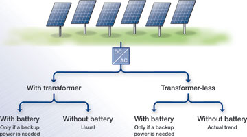
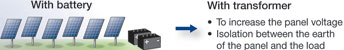
Whether grid-connected or off-grid, all PV installations demand accurate measurement of generated current, both for efficient control of the inverter, and for protection purposes. Connection of the solar array through an inverter to the grid can be made either by using a transformer or directly without a transformer. Transformerless installations have no galvanic isolation, with a consequent risk of leakage to earth. Both configurations may also be used with or without energy storage in a battery. Depending on the purpose (size, efficiency, weight, range, galvanic insulation), today’s market offers a choice of different inverters, each with their own advantages and drawbacks.
Four main inverter designs are commonly encountered. Two designs use a transformer (at low or high frequency) and two designs are transformerless, with or without a DC chopper or step-up converter.
MPPT control, inverter control and protection
For each different topology, the current and voltage measurement is carried out on the DC output of the solar panel, in order to determine current and voltage generated, and to define the MPP (maximum power point) where the maximum output wattage can be extracted from the solar panel.
Current measurement is also needed as an input to the control loop of the inverter, and to ensure protection against short circuit or overload. Open-loop and closed-loop Hall effect technologies are used for the current and voltage transducers.
DC current injection measurement
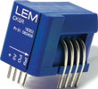
In transformerless designs and in high-frequency transformer configurations, the DC current injected into the grid must be limited to a maximum value of between 10 mA and 1 A, according to different standards that apply in different countries (relevant standards include IEC 61727, IEEE 1547, UL 1741 and VDE 0126-1). This necessitates use of transducers with very high accuracy (better than 1%) and very low offset and gain drifts; a suitable technology is LEM’s closed loop fluxgate transducer (Photo 1).
Leakage current measurement
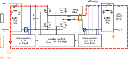
Transformerless inverters without galvanic isolation have a potential for leakage currents to occur. From the simplified representation (Figure 4) of a transformerless inverter design (without taking into account interaction between major elements the PV panel, the AC filter, and grid impedance), the potential hazards are:
* Leakage capacitance between solar panel and roof may offer a path for leakage current.
* Any leakage path from the AC line back to the panel can raise the panel itself to line voltage, leading to a risk of electrical shock to any person who touches it.
* Leakage current can cause electromagnetic interference, grid current distortion and additional losses in the system (depending on PWM).
For safety reasons, therefore, it is a requirement to monitor leakage current, and as a safety device, it is desirable that the measurement be non-contact and non-intrusive. Any AC, 50/60 Hz, leakage currents will be small, up to 300 mA (as typical value, or more, depending on the capacitance due to the solar panel roof configuration) and is measured as the residual component remaining from a differential measurement of currents in several conductors.
Special care is also brought to the sudden variations of 30 mA in leakage currents, attesting a contact of solar panels by a person. The transducer used must measure these fluctuations. Once again, requirements include accuracy and, especially, low offset and gain drifts, to ensure resolution of these small measured currents. The ability to accommodate several conductors, to cater for single- or three-phase systems within the transducer aperture is a major advantage.
This article will continue in the next edition of Dataweek, where earth fault measurement and other topics will be covered.
| Tel: | +27 11 626 2023 |
| Email: | [email protected] |
| www: | www.denver-tech.co.za |
| Articles: | More information and articles about Denver Technical Products |


© Technews Publishing (Pty) Ltd | All Rights Reserved
 printer friendly version