
A MEMS microphone IC is unique among Analog Devices’ products in that its input is an acoustic pressure wave. For this reason, some specifications included in the data sheets for these parts may not be familiar, or familiar specifications may be applied in unfamiliar ways. This application note explains the specifications and terms found in MEMS microphone data sheets so that the microphone can be appropriately designed into a system.
Sensitivity
The sensitivity of a microphone is the electrical response at its output to a given standard acoustic input. The standard reference input signal for microphone sensitivity measurements is a 1 kHz sine wave at 94 dB sound pressure level (SPL), or 1 pascal (Pa, a measurement of pressure). A microphone with a higher sensitivity value has a higher level output for a fixed acoustic input than a microphone with a lower sensitivity value.
Microphone sensitivity in decibels (dB) is typically a negative number; therefore, a higher sensitivity is a smaller absolute value. It is important to note the units presented with the sensitivity specifications of the microphone. It is incorrect to directly compare the sensitivity of two microphones if the sensitivity is not specified with the same unit.
For analog microphones, the sensitivity is typically specified in units of dBV, that is, decibels with reference to 1,0 V rms. For digital microphones, the sensitivity is typically specified in dBFS, that is, decibels with reference to a full-scale digital output (dBFS). For digital microphones, a full-scale signal is defined as the highest signal level that can be output from the microphone; for Analog Devices MEMS microphones, this level is 120 dB SPL. See the ‘Maximum acoustic input’ section for a fuller description of this signal level.
Sensitivity is the ratio of the input pressure to the electrical output (voltage or digital word). For analog microphones, sensitivity is typically measured in mV/Pa. This measurement is converted to a decibel value with the following equation:

where OutputREF is the 1000 mV/Pa reference output ratio. For digital microphones, sensitivity is measured as a percentage of the full-scale output that is generated by a 94 dB SPL input. For a digital microphone, the conversion equation is:

where OutputREF is the full-scale digital output level (1,0).
Higher sensitivity does not always indicate a better microphone. A microphone with higher sensitivity typically has less headroom between the output level under typical conditions, such as conversational speech, and the maximum output level. In near-field (close-talking) applications, a microphone with higher sensitivity is more likely to cause distortion. This distortion often reduces the overall dynamic range of the microphone.
Directionality
Directionality describes the pattern in which the microphone’s sensitivity changes when the sound source changes position in space. All Analog Devices MEMS microphones are omnidirectional (or omni), which means that they are equally sensitive to sound coming from all directions, regardless of the orientation of the microphone. Figure 1 shows a two-axis polar plot of the microphone’s response. This plot looks the same regardless of whether the microphone’s port is oriented in the x-y, x-z or y-z plane.
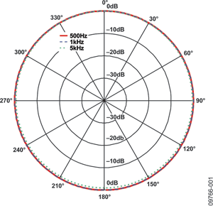
The directional response of a system may not be omnidirectional when an omni microphone is designed into a larger enclosure, such as a cellphone. For the system designer, an omnidirectional microphone provides greater flexibility in the design of the system response to an acoustic input than if the microphone itself has a directional response.
Multiple omnidirectional microphones can be arranged in arrays to create various directivity patterns and for beam forming applications.
Signal-to-noise ratio
The signal-to-noise ratio (SNR) specifies the ratio of a reference signal to the noise level of the microphone output. This measurement includes noise contributed by both the microphone element and the ASIC incorporated into the MEMS microphone package. The SNR is the difference in decibels between the noise level and a standard 1 kHz, 94 dB SPL reference signal.
SNR is calculated by measuring the noise output of the microphone in a quiet, anechoic environment. This specification is typically presented over a 20 kHz bandwidth as an A-weighted value (dBA), which means that it includes a correction factor that corresponds to the human ear’s sensitivity to sound at different frequencies. When comparing SNR measurements of different microphones, it is important to make sure that the specifications are presented using the same weighting and bandwidth; a reduced bandwidth measurement makes the SNR specification better than it is with a full 20 kHz bandwidth measurement.
Dynamic range
The dynamic range of a microphone is a measure of the difference between the loudest and quietest SPLs to which the microphone responds linearly. The dynamic range of a microphone is not the same as its SNR (in contrast with audio ADCs or DACs, where the dynamic range and SNR are typically equivalent).
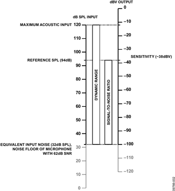
The SNR of the microphone measures the difference between the noise floor and a 94 dB SPL reference, but the microphone still has a great deal of useful signal response above this reference level. The microphone responds linearly to acoustic signals from 94 dB SPL up to the maximum acoustic input of 120 dB SPL. Therefore, the dynamic range of a MEMS microphone is its SNR + 26 dB, where 26 dB = 120 dB –94 dB. For example, the ADMP404 with an SNR of 62 dB has a dynamic range of 88 dB.
Figure 2 shows the relationship between an acoustic input measured in dB SPL and a microphone’s voltage output in dBV. The dynamic range and SNR measurements are shown between these two scales for reference. Figure 2 uses an ADMP404 with a -38 dBV sensitivity and 62 dB SNR to show these relationships.
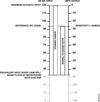
A similar relationship between dB SPL input and dBFS output for digital microphones is shown in Figure 3. Note that in this figure, the maximum acoustic input of 120 dB SPL is mapped directly to a 0 dBFS output signal. As long as the maximum acoustic input corresponds to 0 dBFS and is set at 120 dB SPL, a digital microphone always has a sensitivity of –26 dB. This is a function of the definition of sensitivity being measured at 94 dB SPL and is not a design parameter that is adjustable by changing the gain of the microphone ASIC.
Equivalent input noise
Equivalent input noise (EIN) is the output noise level of the microphone, expressed in SPL, as a theoretical external noise source placed at the microphone’s input. Input SPLs below the EIN level are under the noise floor of the microphone and outside the dynamic range of signals for which the microphone produces an output. EIN can be derived from either the dynamic range or SNR specification as follows:
EIN = maximum acoustic input – dynamic range.
EIN = 94 dB – SNR
The EIN of a microphone with 62 dB SNR and 120 dB maximum acoustic input is 32 dB SPL – approximately the SPL that would be generated by a soft whisper in a quiet library at a distance of 5 metres. Figure 2 and Figure 3 show the EIN of the microphones.
Frequency response
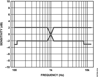
The frequency response of a microphone describes its output level across the frequency spectrum. The high and low frequency limits are described as the points at which the microphone response is 3 dB below the reference output level at 1 kHz. The reference level at 1 kHz is customarily normalised to 0 dB. Using these conditions, Analog Devices MEMS microphones typically have a uniform frequency response from 100 Hz to 15 kHz.
The frequency response specification also includes the deviation limits from a flat response within the pass band. These values, expressed as units of ±x dB, show the maximum deviation of the output signal from a nominal 0 dB level between the -3 dB points.
For Analog Devices MEMS microphones, the low-frequency roll-off below the lower –3 dB point is first order (6 dB/octave, or 20 dB/decade). The high-frequency roll-off above the upper –3 dB point is second order (–12 dB/octave, or –40 dB/decade).
The data sheets for MEMS microphones show this frequency response in two figures: one figure shows the frequency response mask and the other figure shows the typical measured frequency response. The frequency response mask figure shows the upper and lower limits of the microphone output across frequency; the microphone output is guaranteed to be within this mask. The typical frequency response figure shows an actual microphone’s response across the frequency band. Figure 4 and Figure 5 show examples of these two plots taken from the ADMP404 data sheet.
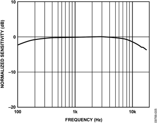
A microphone with a wide, flat frequency response helps in the design of systems that require natural sound and high intelligibility.
Total harmonic distortion
Total harmonic distortion (THD) is a measurement of the level of distortion on the output signal for a given pure tone input signal. This measurement is presented as a percentage. This percentage is the ratio of the sum of the powers of all harmonic frequencies above the fundamental frequency to the power of the tone at the fundamental frequency.
A higher THD measurement indicates a higher level of harmonics present at the output of the microphone. The THD of the MEMS microphones is calculated from the first five harmonics of the fundamental.
The input signal for this test is typically at 105 dB SPL, which is 11 dB above the reference SPL of 94 dB. THD is measured at a higher SPL than other specifications because, as the level of the acoustic input signal increases, the THD measurement typically increases as well. A rule of thumb is that the THD triples with every 10 dB increase in input level. Therefore, THD less than 3% at 105 dB SPL means that the THD will be less than 1% at 95 dB SPL.
This measurement is not to be confused with total harmonic distortion plus noise (THD + N), which measures not only the level of the harmonics but also all other contributions to noise on the outputs.
Power supply rejection ratio
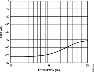
The power supply rejection ratio (PSRR) of a microphone is a measurement of its ability to reject noise present on the power supply pins from the signal output. PSRR is measured by superimposing a 100 mV peak-to-peak sine wave at 217 Hz on the VDD pin of the microphone. The PSRR measurement shows by how many decibels this input signal is attenuated when seen at the output of the microphone. This specification is shown at 217 Hz because, in GSM phone applications, the 217 Hz switching frequency is typically a dominant source of noise on the power supply.
The data sheets for MEMS microphones also show the PSRR across the 100 Hz to 10 kHz frequency range. These microphones have excellent low-frequency noise rejection (<-70 dBV for analog microphones and <-80 dBFS for digital microphones). As shown in Figure 6 (taken from the ADMP404 data sheet), PSRR increases to a level just under –50 dB at high frequencies.
Maximum acoustic input
The maximum acoustic input is the highest acoustic sound pressure level (SPL) that the microphone can tolerate. SPLs higher than this specification cause severe nonlinear distortion of the output signal. Maximum acoustic input is specified in peak SPL, not rms level.
The maximum acoustic input of the Analog Devices MEMS microphones is 120 dB, which corresponds to a sound pressure level in air of 20 Pa.

© Technews Publishing (Pty) Ltd | All Rights Reserved