


In the 1970s and 1980s, calibration standards known as multifunction calibrators began to replace instruments that could provide calibrations for only one or two electrical quantities. These new instruments could provide, in a single enclosure, direct voltage, alternating voltage, resistance, direct current and alternating current for the calibration of a wide range of digital multimeters.
In the 1990s, multiproduct calibrators were introduced with the goal of supporting the calibration needs of a wide range of workload including DMMs, thermocouple thermometers, RTD thermometers, capacitance meters, chart recorders, oscilloscopes and wattmeters. Some of the features incorporated in these new calibrators make wattmeter calibration even easier and more accurate.
Traditional power calibration
Even though multifunction calibrators could source voltage or current, they were not capable of providing these basic power calibration signals simultaneously.
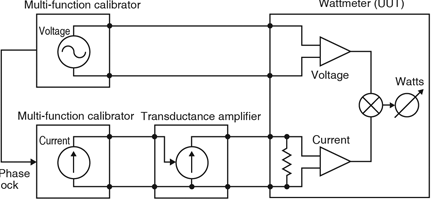
Power calibrations have been performed using ‘golden standards,’ other wattmeters used as transfer standards, power calibrators, expensive systems dedicated to power calibration, or phase locking multiple multifunction calibrators together. Figure 1 shows such a multifunction calibrator system for the calibration of single-phase wattmeters. It consists of separate calibrators for voltage and current, as well as an amplifier to provide higher currents to the UUT (unit under test). A three-phase system would take six calibrators and three amplifiers.
Power calibration using a multiproduct calibrator
Figure 2 shows the same wattmeter calibration with a single multiproduct calibrator. It is able to perform this calibration thanks to the ability to output voltage and current simultaneously, and to control the phase relationship between them. In addition, the multiproduct calibrator can source up to 20 A without the need for an additional current amplifier.

The Fluke 5520A multiproduct calibrator allows locking the phase relationship precisely between multiple units, allowing three-phase power to be calibrated easily with three calibrators. Because the phase relationship between outputs can be controlled, the current outputs of multiple calibrators can be summed as well. This means that a three phase calibration system can be used to output current or single-phase calibrations of up to 60 A. Figure 3 shows a simplified block diagram of the 5520A.
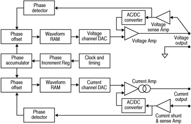
The clock and timing circuit causes the phase accumulator to be incremented in regular intervals by the phase stored in the phase increment register. The waveform RAM is addressed by this value offset by the value in the phase offset register. Two phase offset registers are provided to allow each channel to be offset relative to a master ‘start-of-record’ sync pulse.
This sync pulse allows one calibrator designated as the master to provide the clock and a sync pulse to other units so three-phase calibrations can be performed with the ability to set the phase of each of the six outputs in any relationship to the others. Dual phase offset registers allow another important feature of the calibrator. The phase of each channel is sensed at the output and the phase offset register adjusted to compensate for any phase shifts due to loading effects.
Power calibration presents unique design challenges. Some are described below not only to show some of the design aspects of such a calibrator but also to indicate some of the hazards to the preservation of accurate signals external to the calibrator.
Uncertainty analysis
For a complex parameter such as power, the uncertainty analysis can be quite complex as well. To aid a simplified analysis, consider the following equation:
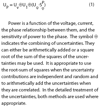
Because the calibrator can operate over a wide range of voltages, currents, frequencies and phase angles (power factors), crosstalk between the voltage and current is a factor that must be considered. The expression of uncertainty in Equation 1 is expanded in Equation 2 to show the contribution to uncertainty due to crosstalk.
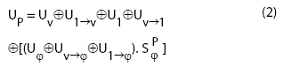
Equation 2 tells us that the uncertainty in power is a function of the uncertainties in voltage, the influence of current upon the voltage, current, the influence of voltage upon current, phase, the influence of voltage on the phase, the influence of current on phase and the phase angle itself.
Voltage uncertainty
Voltage uncertainty was improved considerably in the 5520A, but primarily for meter calibration. For power calibrations, it is always combined with other uncertainties which are larger and therefore is never the largest contributor to the overall uncertainty. The voltage is sensed at the output binding posts but some care must still be taken to ensure that the loading imposed on the voltage output is within the calibrator’s specifications.
Voltage uncertainty due to current
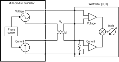
Shifts in the output voltage can occur as a function of the current channel affecting calibrations at high currents with low voltages. Fluke’s tests indicated that these shifts could be fairly accurately modelled as a mutual inductance, M, between the current carrying leads and the voltage or voltage sensing leads. This coupling can occur in the calibrator, the UUT, and the interconnections in either the high or low leads.
A mutual inductance between the high current lead and the low of the voltage output is shown in Figure 4. Since the mutual inductance internal to the instrument can be quantified and its effects are calculable, the degradation due to internal mutual inductance was reduced significantly. The voltage induced by the current, I, at frequency, f, is V = 2πMI. However, this induced voltage leads the current waveform by approximately 90° in phase.
At unity power factor, with voltage and current in phase, it also leads the voltage waveform by 90°, resulting in little error. As the phase, φ, changes between the channels, the error increases proportional to sin φ. The error voltage, Ve, is that contribution of this interfering signal which is in phase with the voltage channel, 2πMIsin φ.
Current uncertainty
For lower frequencies, at unity power factor, the uncertainty of the current is the largest contributor to the power uncertainty. Therefore, considerable effort was made in the design to maintain current accuracies.
Current uncertainty due to voltage
Similar to the coupling of current into voltage, the voltage channel can be coupled into the current channel. In most cases, the coupling mechanism can be modelled as a stray capacitance. If the voltage and current channels were isolated, the capacitance would cause only a common mode signal to be coupled from the voltage channel to the current channel. However, so that the microprocessor can control both channels without having to design isolated digital control circuitry, it is required that the lows of the current and voltage channels be common to within a few tenths of a volt.
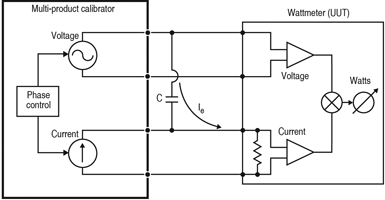
This connection may be made in the calibrator, in the UUT, or externally. Even if the channels were isolated, it is unlikely that the isolation to earth would be less than the tenths of a picofarad required to keep the errors manageable. Internal to the calibrator, this capacitance is calculable and stable and its effects can be taken into account arithmetically with the calibrator’s microprocessor. Externally, when high voltages are used with relatively low currents, the high-voltage lead should be shielded and not run too close to the current leads.
The error current, Ie, lags the voltage channel in phase by 90°, making the magnitude of the signal which actually interferes with the magnitude of the current channel, 2πCVsin φ.
Phase uncertainty
The uncertainty in power due to phase is a function of both the uncertainty of the phase and the phase itself, and approaches infinity at 90°:
For more information contact Comtest, +27 (0)11 608 8520, [email protected], www.comtest.co.za
| Tel: | +27 10 595 1821 |
| Email: | [email protected] |
| www: | www.comtest.co.za |
| Articles: | More information and articles about Comtest |


© Technews Publishing (Pty) Ltd | All Rights Reserved
 printer friendly version