


Nigel Adams of Aeroflex discusses how the company approached a customer problem that required a series of RF tests in conjunction with digital functional testing and a complex fixturing solution.
A product that is not wireless-enabled is becoming almost a rarity these days. Even day-to-day items in the street are becoming RF capable.
Let us consider the humble streetlight, a seemingly simple device, a lamp and lens/cover mounted on a support pole with a direct power feed and coupled to a time switch or light sensor to control operation. Apart from the materials used in its construction and some improvements in light output versus power efficiency, the standard streetlight has changed very little in the years since it replaced the gas lamp. Now, with the drive for better control and more energy efficiency, the world of RF control has finally reached the streetlight.
An innovative system has been developed by a UK-based company that has the potential to spread worldwide. The system offers a number of useful features to the installer and operator, as well as providing lower operating costs to the local population (who are also the financier through local taxation).
This new control method offers the following features:
* Remote switching of the lamp.
* Monitoring of power consumption.
* Lamp hours used.
* Dimming of lamp.
* Lamp strike event logging.
* Identification of lamp failure.
The main active component of the system is a small RF module that is fitted to each individual street lamp which is controlled from a hub that can handle up to 255 lamp units. In turn, the hub communicates with the base network via a GSM phone link connected through the Internet to a local control centre. Additionally a GPS module identifies the exact location of the hub and it can pass this data back to the monitoring centre.
The initial production test for such a unit was to simply apply power and observe whether the RF modules transmitted a signal. While it was a basic go/no-go test there was no parametric analysis of signal strength or product quality and for this reason a more in-depth test strategy would need to be adopted.
The following discusses how Aeroflex approached the different aspects of this project and provided a high-quality solution which has proven to offer significant throughput increase and capability with great flexibility in test.
Solution
As a leader in both production and wireless test, Aeroflex proposed a solution that provides a screened environment for the individual unit under test (UUT) and allows the programming of each unit together with measurements of all the important parameters to qualify the unit performance.
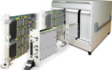
At the heart of the solution is the Aeroflex 5800 series multistrategy test system. Its digital functional hardware, combined with the Aeroflex 3000 series PXI RF instrumentation, provided a comprehensive means of test capability.
Application
The application uses a combination of the Aeroflex test language known as AIDE (Aeroflex Integrated Development Environment) and elements of bespoke code written in C#. Due to the .NET compliance built into both languages, it has proved simple to interface between them as required. This also provides an element of future proofing should any further solution developments be required.
A simple graphical user interface (GUI) was created that gave the operator good feedback on all elements of the test process as well as giving simple quality statistics for yield and trend over recent test events. All data is logged to the Aeroflex data management system i-Base for ongoing quality and traceability recording. In addition, to ease use, characterisation of the RF test sites and air attenuation performance parameters are stored in easily updated configuration files.
The application generates and maintains a record of the product serial numbers in use and ensures that the number sequence is not repeated or duplicated at any point. This record is maintained using a series of stub files which are created for each unit once it passes the tests and a backup log record is directed to a remote network drive for safety and security. A label is printed on successful completion of the test sequence associated with the finished units. The format and structure and printing of the label are under direct control of the application.
Full flexibility for configuration and troubleshooting were built into the program as standard so that the application could easily be adapted for different product types and parameter changes should the customer wish to change the product at any stage in the future. All configurable parameters are contained in simply modified text files. This was specifically done to ensure the customer’s engineers did not require specialised knowledge to make common changes.
Fixture
The first solution comprised a screened RF box with a hinged lid that was modified to accept a small fixture base and held the UUT. A secondary hinged cover above the lid provided a pressure plate to ensure the UUT was kept firm against the top face of the lid with the antenna protruding down into the RF chamber. Interlocks in the box lid ensured the power supply was isolated when the lid was opened.
The popular ‘pylon’ style of multipin interface provided the connections between the tester and the fixture along with the usual power and control requirements. Using this method of interconnection provided a standardised interface which offered good performance and repeatability within a tight solution budget.
Two different models of the unit casing meant that the fixture location had to cope with both types. This was achieved by using a two-sided toggle clamp with the operator simply turning it to the correct side depending on which device type was being produced.
As product demand dictated, a second fixture solution was developed building upon the experience gained with the initial fixture but with a mind towards maximising throughput.
The approach adopted was a dual-bay solution with individual RF chambers and removable plates for each product type. This allows rapid product changeover when required. Only four thumbscrews were needed for correct positioning and alignment of the product plates. All power supply and personality controls/switching were housed in the main fixture base. As many parts as possible were made interchangeable to provide simple fault tracing and the ability to keep a single chamber operating should the need for repairs be required.
Each RF screened chamber contained three antennas, each tuned to the target frequencies currently in use. The antenna is removable such that if any changes occur in the future it will be simple to update to the new frequency range by swapping the aerial and amending the relevant application configuration file(s) with the new values.
Product test
The tests required both receiver and transmitter testing; essentially the product behaved in a similar way to a radio modem. The modulation pattern being a fairly common FSK pattern, it was a simple matter to specify the hardware from the standard Aeroflex range of PXI instruments. Thus, a 3020A RF signal generator and a 3030A RF digitiser along with their accompanying local oscillators (3010/3011) were specified. Signal switching to the various antennas was accomplished using two 3061 RF combiners to handle the two fixture sites (as used in the later fixture solution).
Use of the combiners in the RF path also provides simple loopback routing for self-test purposes and provides confidence in the main signal path and performance verification. Thus rapid identification of any potential fault condition may be achieved.
In operation, two processes are carried out. The first action is to program the onboard controller with the basic run code and then perform a calibration function where the transmitted frequency is measured and compared against a stored reference. The difference is calculated and the offset is programmed back into a PIC device using the Aeroflex 5800 digital functional hardware, thus ensuring that all units will maintain their specified frequency range.
On power-up the device would transmit bursts of signal which were analysed for accuracy of centre frequency and transmitted power as well as the actual information in the data stream. A bit error rate (BER) test was also carried out at the end to ensure that the radiated signal closely matched the same data sent down a cable connection. At this point the devices were subjected to a conformal coating to protect the sensitive electronics from the harsh life at the top of a lighting standard and the weather.
The second process is essentially a repeat of the RF testing phase to ensure the coating has not caused any appreciable degradation in performance. As product demand further increased, a need arose for additional frequencies to be tested for product use in other countries. This was easily handled within the software through a simple lookup table.
Solution benefits
Accuracy and test speed were both much improved, compared to the manual method. It was now possible to provide a means of ‘grading’ the performance of the units into those that had exceptional performance and units of standard performance. This was useful in areas that required a stronger signal due to a more difficult operating environment.
One additional benefit appeared early on in the use of the system where a large number of units were discovered to have a low power output. This was traced to an incorrect value inductor fitted in the RF section of circuitry, which transpired to be a wrongly marked component from a supplier.
If this fault had remained undetected it could have proved very costly to rectify once the units had been installed on lamp posts. The time and cost of sending operators out with specialised equipment would be very damaging to the effective cost management of a project, not to mention the supplier reputation.
In the first six months of the system being commissioned, the production quantity was over 30 000 units. Since that time the demand has risen to virtually double this number and almost quadruple the original go/no-go test prior to the test system being installed.
Upgrading
It was always part of the project to provide an upgrade path to allow additional test techniques and capability to be added. This was to increase product throughput as well as improve quality of test. Due to the product’s success in the marketplace it was soon clear that greater production capacity was required if supply was to keep pace with demand.
Overall test time was governed by the device performance rather than any limitation of the tester hardware. The decision was taken by the customer to add a new fixture to the original test solution to effectively double the throughput. After discussion with Aeroflex engineers this was amended to create a completely new fixture that had a dual bay capability and also allowed for additional product types now being developed, to be easily tested on the same hardware with only a simple personality plate being required to cope with the new product type.
Conclusion
By partnering with Aeroflex as a solution provider with wireless and product test expertise, together with Aeroflex’s product ranges, the end user has been able to quadruple output and provide quality products to their customers within a tight budget.
After just over one year since the project was conceived, Aeroflex received an order for a further 5800 and duplicate dual bay fixture to cope with the ever increasing demand.
| Tel: | +27 12 452 0400 |
| Email: | [email protected] |
| www: | www.measuretest.co.za |
| Articles: | More information and articles about Measuretest |


© Technews Publishing (Pty) Ltd | All Rights Reserved
 printer friendly version