The convenience and reliability of portable electronic devices depend on efficient management of batteries and their limitations. One universal, not to mention irritating, limitation of all (chemical) batteries is their finite capacity and lifetime. Moreover, while the inevitability of eventual discharge is bad enough, the effects of sudden and unexpected battery failure are usually much worse. This makes realtime estimation of remaining battery energy and life expectancy a useful feature in portable systems.
A battery's expected lifetime at any given moment is equal to remaining battery charge divided by load current: TB = QB/IB. Measurement of IB is easy enough, but we also need QB to predict battery life expectancy.
The simplest way to obtain QB is to estimate it from the battery output voltage. Unfortunately, the exact relationship of battery voltage to charge is a dauntingly messy nonlinear function of many parameters. Included among these are initial capacity, temperature, load current, discharge history, and battery chemistry (alkaline, NiCd, LiMnO2, etc). Even so, a usable approximation of QB can be obtained by using a simple linear model derived from a least-squares method. These are fit to the actual discharge curves of various popular battery types.
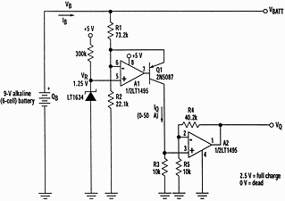
The circuit in Figure 1 is based on this idea. It outputs a 0 to 2,5 V signal that is proportional to the estimated remaining battery capacity. The circuit can be adapted to different battery voltages and types by proper selection of R1 and R2. This allows IQ to vary from 50 to 0 µA as battery charge varies from 100% to 0%. Then, the fixed-gain current-to-voltage converter A2 produces the calibrated output voltage.

Listed below are the least-square R1/R2 approximations for four of the most popular battery chemistries (normalised to NCELLS = the number of cells in the battery; VR = the 1,25 V reference voltage):
Alkaline: R1 = 12,2K x NCELLS
R2 = VR x R1/(0,72 x NCELL-1)
LiMnO2:R1 = 16,8K x NCELLS
R2 = VR x R1/(1,85 x NCELL-1)
NiCd: R1 = 6,83K x NCELLS
R2 = VR x R1/(0,82 x NCELL-1)
Pb-Acid: R1 = 6,76K x NCELLS
R2 = VR x R1/(1,43 x NCELL-1)
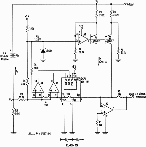
Translation of estimated battery charge to estimated life expectancy is more complicated due to the required arithmetic division of charge by load current. Figure 2 shows one way to implement this calculation by making A2's transimpedance gain variable (inversely proportional to IB) instead of fixed as in Figure 1. Key to this method is the addition of digitally controlled potentiometer DCP1 (a Xicor X9511 'PushPot').

In operation, comparators A3 and A4 match VS, the voltage developed across load-current sense resistor R4, to the voltage at DCP1's VL pin. As the load current increases, A3 asserts DCP1's PD (decrement) control pin. This causes the VW wiper to step toward the VL pin and drive RL and VI toward zero.
Conversely, as load current decreases, A4 asserts DCP1's PU (increment) pin, driving the wiper toward VH and RL toward 10k. This establishes a feedback loop that continuously maintains: RL = 10k(1-ILR4/0,05 V). In other words, as IL goes from 0 to full-scale defined by 0,05 V/R4, RL goes from 10k to zero. The internal structure of DCP1 inherently establishes RH = 10k-RL, so RH = 10k x ILR4/0,05. Since A2's transimpedance gain is given by R32/RH, the gain is R32/(10k x ILR4/0,05) = ~10k/IL. A2's gain is, as promised, inversely proportional to IL.
With the component values shown, Figure 2 will work with a standard 9 V, 500-mA-hr alkaline battery and 100 mA < IB < 1 A. Together, they generate an output scaled to 1 V/hr of remaining battery life. Appropriate selection of resistors R1 through R4 can accommodate virtually any battery and any desired scale factor.
For further information about Xicor devices contact Rob McMaster, Impact Memec, (011) 897 8600.

© Technews Publishing (Pty) Ltd | All Rights Reserved