


Many industrial/scientific/medical (ISM) band radio frequency (RF) receivers use a simple external data slicer to generate the baseband digital output. These simple baseband systems can generate unwanted digital output when there are no active radio transmissions.
This article provides a basic description of squelch and gives examples for how to implement it in an amplitude-shift keying (ASK)/on-off keying (OOK) or frequency-shift keying (FSK) system.
Radio squelch
Squelch is the process of removing unwanted background noise from a receiver in a way that allows for a strong signal to be decoded while weak signals near the level of the receiver’s sensitivity are rejected.
A common example is available on most walkie-talkies or citizen band (CB) radios where an adjustment knob can increase the squelch level and suppress unwanted audio noise when no transmission in detected.
Similarly in a digital radio system, squelch can be used to suppress unwanted digital output or toggling on the data line when no detectable transmission is present. ‘Breaking squelch’ is a common term used to indicate that a received signal has risen above the power threshold, and thus indicates a strong enough transmission is present.
Baseband decoding
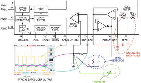
All of Maxim’s industrial/scientific/medical (ISM) radio-frequency (RF) receivers include simple baseband-decoding hardware that consists of a Sallen-Key data filter, a comparator or data slicer, and at least one peak detector. Often the peak detectors go unused, but they can be a convenient way of increasing the responsiveness of the baseband decoding of an initial incoming transmission.
The data slicer is the heart of the baseband system and is used to convert the demodulated analog signal into a digital signal for use by the microcontroller or other digital decoding unit.
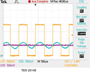
The common configuration used with a data slicer is to have the baseband analog signal connected to the positive input of the comparator, while the negative input is connected to a low-pass filtered version of the same analog signal. Figure 1 shows a typical schematic of a baseband system with a scope plot that depicts the signals commonly found on the respective pins.
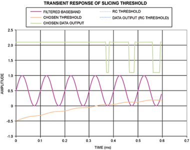
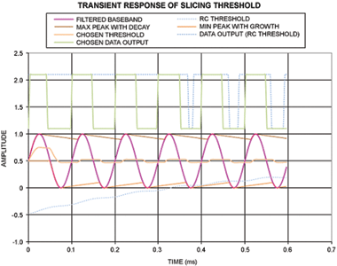
Simulated versions of the baseband circuit can be used to show various responses of the system. When a simple resistive-capacitive (RC) slicer level is implemented, there are a few limitations that will impact the accuracy of the output data (Figures 2 and 3).
By introducing a peak detector, the output data line can react to the first bits received by ‘jumping’ the slicing threshold to a higher level very quickly (see Figure 4).
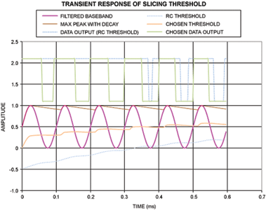
Finally, with the use of both maximum and minimum peak detectors, the threshold is quick to reach the centre of the baseband signal and can thus respond to the first data bit received and has the best response for accurate duty cycle of the data output signal, as seen in Figure 5.
Implementing ASK squelch
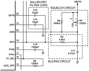
Adding squelch to an ASK or OOK system involves offsetting the threshold voltage from where it would normally settle, based on noise power alone. This offset process is commonly accomplished by adjusting the slicing level with the use of a fixed voltage-divider circuit.
In Figure 6, the DSN line is pulled up slightly to the supply rail with a 200 kΩ resistor. This design was implemented with a potentiometer (R5) which, if populated in exchange for the R6 pull-up resistor, would permit the user to manually adjust the amount of positive offset applied to the DSN line.
The advantage of this method is the simple reduction or elimination of any ‘chatter’ or unwanted digital output.
Unfortunately there are two possible negative impacts. The first is a slight reduction in receiver sensitivity. This comes from the direct trade-off between having the output data constantly reacting to the analog signal based on an average comparison voltage versus adjusting that level so that noise does not cause data transitions.
The second impact is a slight skewing of the digital output signal’s duty cycle. The change in duty cycle is a result of not having a slicing level that is an exact average between a peak and valley of the analog output. To some extent, using a Manchester encoding scheme can eliminate this issue.
Implementing FSK squelch
Whereas ASK squelch is an easy process to implement with most inherent receiver baseband architectures, FSK squelch is a different matter.
In an ASK system, the slicing level will tend to settle at the average noise level because of the method used to establish a comparison signal. In an FSK system, the baseband is configured the same as an ASK system, but the noise profile is different.
With an FSK decoder, the noise spectrum will tend to be white (flat across all frequencies), but the IF filter and the receive signal strength indicator (RSSI) limiting amplifiers have undue influence on the average frequency of that noise.
Because of tolerances inherent in the system, the average noise output could move the comparison voltage either above the mark and space midpoint or more likely below. Because squelch is inherently related to the strength of the incoming signal, users need to incorporate the RSSI output in the squelch system.
A basic design for FSK squelch requires a system that reacts to an RSSI level, has a reference with which to compare the level, and somehow gates the original digital data. In essence, the RSSI level is compared to a reference voltage. If the incoming signal power is above the break level, then the original data is allowed to pass through the system.
This can be accomplished with many different methods, especially when considering the wide variety of microcontrollers available to manage the radio system. An example of a simplified circuit is shown in Figure 7. This is a basic FSK squelch circuit implemented with a matched pair of bipolar junction transistors (BJTs), three resistors and a capacitor.
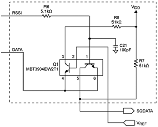
The differential pair is wired as a comparator with VREF and RSSI as inputs to each base. The DATA line is connected as an on/off current source, resulting in a circuit that executes a simple AND gate function. By providing a reference level at VREF (from a basic resistor-divider or digital-to-analog converter) the signal at SQDATA is an RSSI-gated version of the DATA line.
Similar to the ASK squelch system, the advantage is a reduction or elimination of chatter in exchange for a slight reduction in receiver sensitivity. Since this additional circuit does not directly influence the slicing level of the comparator, the FSK squelch has no impact on the digital output signal’s duty cycle. Due to variations in DC offset of the amplified RSSI level, VREF may need to be adjusted individually.
For more information contact Michelle Parreira, CST Electronics, +27 (0)11 608 0070, [email protected],
| Tel: | +27 11 608 0070 |
| Email: | [email protected] |
| www: | www.cstelectronics.co.za |
| Articles: | More information and articles about CST Electronics |


© Technews Publishing (Pty) Ltd | All Rights Reserved
 printer friendly version