


For those wanting to maximise the bandwidth of their oscilloscope for their measurements, an important aspect to consider is what the right probe can do. It is important to select the probe bandwidth relative to the oscilloscope being used, but just as important are the effects of probe grounding on overall measurement bandwidth.
Improper ground selection will drastically reduce system bandwidth and also create distortion on the measured signals. This article will cover four grounding techniques for active probes, the best ground solution, and explain the bandwidth impact associated with each technique.
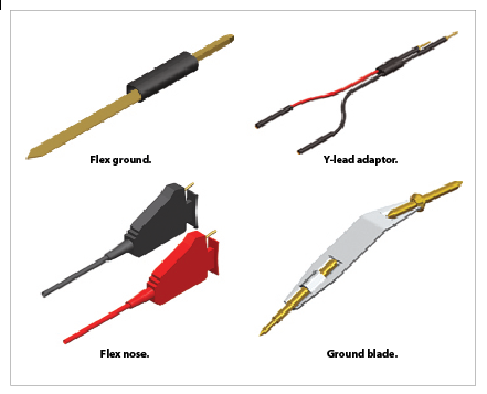
Figure 1 shows the accessories/leads available for one type of Agilent oscilloscope probe. In order for readers to know which one of these to use and how each impacts the performance of an oscilloscope/probe system, this article will walk through four possible probe lead configurations and discuss the benefits and disadvantages of each.
Configuration 1: Hands-free probing with Y-lead adaptor and flex nose clip adaptor
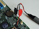
Assume one was using an oscilloscope with 4 GHz of bandwidth. The probe in Figure 2 has an upper bandwidth of 2 GHz. Its input capacitance is below 2 pF, resulting in high input impedance at high frequencies. For these reasons, this active probe will be used as the main example for the remainder of this article.
Figure 2 also shows the active probe attached to a 10 centimetre Y-lead adaptor with a flex nose adaptor accessory. The combination of these accessories gives the user more probing flexibility and a hands-free solution. The flex nose accessory can be hooked to header pins, test points, IC leads and some passive components. However, the added length of these two accessories increases inductance, which severely degrades the bandwidth of the probe.
Using this probing configuration decreases the bandwidth by 1,5 GHz, resulting in effectively a 500 MHz probe. Measurements using this probe tip combination should be used for troubleshooting and looking for signals to be present, but signal integrity and bandwidth should not be scrutinised.
Configuration 2: Hands-free probing with Y-lead adaptor
In this configuration, the flex nose clip adaptor in Figure 2 is eliminated and only the Y-lead adaptor accessory is used. The Y-lead adaptor female pins are then plugged directly into industry standard header pins.
This solution reduces the inductance from the Figure 2 configuration and brings the probe bandwidth up to 1 GHz. However, the best case probe bandwidth is still cut in half. This probing solution should also be used as a rough troubleshooting method and should not be used to analyse a system’s performance relative to the signal seen on the oscilloscope.
Configuration 3: Probing with a copper pad and flex ground solution
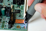
Next, let us transition the measurement method from Y-lead adaptor to the flex ground solution shown in Figure 3. This solution significantly reduces the inductance and the majority of stray capacitance.
The ground blade performs best when used with the self-adhesive copper pad also shown in Figure 2. The copper pad can be cut to fit on top of any IC. Once attached to the IC, the copper pad should be grounded to a few of the IC grounds using shorting wires.
This solution is effective for probing signals with high-frequency content. However, to maximise this solution’s performance one should ground the copper pad in as many places as possible. The resulting performance is around 1,8 GHz, only 200 MHz away from the maximum bandwidth of this active probe.
Configuration 4: Probing with a ground blade solution
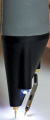
Now consider a switch from the copper pad and flex ground configuration to the ground blade configuration shown in Figure 4. This solution will provide maximum probing bandwidth.
The probe in Figure 4 has replaceable tips (both rigid and spring tips). It is preferable to use the spring tip as the ground blade is also spring loaded. This allows Z height flexibility while probing.
To change the probe tip, pliers should be used to grip the tip and pull it straight out of its contact socket along the axis of the probe. One should not grip the plastic insulator of the probe with the pliers or the tip could be crushed and the tip may no longer be able to be removed from the probe tip socket.
The spring tip is then inserted with pliers into the contact housing along the axis of the probe. In order to properly insert the spring tip completely into the housing, the probe tip should be carefully pressed against a hard surface.
Note that the ground blade is designed with a bend and can pivot, giving the user an adjustable pitch to find the closest ground possible while still connected to the signal target. This probing solution results in the probe’s highest signal bandwidth of 2 GHz.
Measurement results
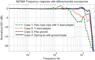
Figure 5 shows all four configurations covered in this article. It is clear that while configurations 1 and 2 provide hands-free probing solutions, the bandwidth and signal integrity suffer relative to configurations 3 and 4.
The lead length of the Y-lead adaptor adds inductance and stray capacitance, creating a resonant circuit. The effects of this circuit are seen in the green and red lines in the form of ripple and frequency roll-off well before the 2 GHz point.
Taking away the Y-lead adaptor and reducing the ground length to the shorter flex ground accessory, flattens the response and improves bandwidth as shown in the blue line. However, using the ground blade solution gets the tip and the ground closer together for minimal ground inductance and stray capacitance, resulting in a 2 GHz frequency response well above the 3 dB point (see the black line in Figure 5).
Also note that the circuit under test may perform differently without the probe attached. This is due to capacitive loading induced by the probe. However, a high-impedance/low-capacitance probe designed for high-bandwidth circuits will reduce this.
Conclusion
The purpose of the four configurations shown in this article was to investigate the most accurate signal measurement possible and pass it through the probe to the oscilloscope. The resultant waveform on the oscilloscope will now most accurately represent the signal from the device under test.
It is important to remember that there will always be a trade-off between measurement flexibility, usability and resulting bandwidth. Added inductance can bring with it stray capacitance, creating RC circuits that resonate within the measured bandwidth.
These circuits will reduce bandwidth and the ripple that has been discussed will impact amplitude readings. For example, users can use longer lead solutions for quick checks to ensure that circuits are functioning. However, for critical measurements, lead length (both on the signal and ground side) should be kept to a minimum.
| Tel: | +27 12 678 9200 |
| Email: | [email protected] |
| www: | www.concilium.co.za |
| Articles: | More information and articles about Concilium Technologies |


© Technews Publishing (Pty) Ltd | All Rights Reserved
 printer friendly version