


New, high-performance telcom/data transmission applications, supported by fast bus driver ICs, require optimum connectors especially designed for data transfer point-to-point applications. The significance of simulation in design flow is vital.
High signal integrity and contact density are required in today's communication connectors. The ERmet ZD connector family (Figure 1) includes straight 'male' with press-in contacts plus 'female' right-angle press-in or SMT versions which satisfy the demand for signal integrity and contact density in data transmission applications of 5 Gbps and above. ZD indicates impedance controlled (Z) and (D) differential data transmission.
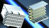
As many backplanes use pressfit technology the straight male ZD generation of connectors is available in pressfit together with application tooling. For rational mounting and optimum signal integrity the right-angle ERmet ZD female connectors used on the daughtercards are available in pressfit or SM versions. SMT signal contacts and THT screen contacts give low crosstalk and minimal reflection allowing high data transfer rates and good signal integrity. Hence the design principle of the new connector module made up of contact wafers with vertical screening of each contact pair for differential data transmission.
For flexible routing and maximum signal integrity, a 2,5 mm raster was selected for the ERmet ZD connector family. This slightly larger raster (Figure 2) has the benefit of wider tracks. The data transmission quality of differential signal pins is influenced by the geometry of the PCB stack width/s and PCB material.
Dielectric losses and frequency dependent AC losses (copper track skin effect) have a large influence on lead stability. At high speeds, skin effect has a decisive effect on total losses which results in reduction of signal amplitude. Skin effect losses are compensated by wider and thicker copper tracks. At a contact raster of 2,5 mm in relation to the contact rows, the distance of wafers between ground and signal contacts is 1,5 mm. The sequence in the row is therefore ground-signal-ground, whilst on the wafers the sequence is ground-signal-signal-ground.
Three or four shielded contact pairs are available per contact row, separated from each other by 4,5 mm. This gives a total of 160 differential contact pairs per 100 mm length. Module lengths of 50 and 25 mm are planned in the four contact pair version and 50, 42,5, 37,5 and 25 mm in modules with three contact rows. The configurations with three contact rows are designed specially for Eurocard format backplane layouts with 0,8" card pitch. Shielding between the differential contact pairs is an L-shaped basic form and is implemented so that the individual wafers are comprehensively shielded. In order to achieve this, appropriately designed shielded plates are integrated vertically between the contacts.
In the male connector, contacts have three mating levels. Thus, when mating the connector, the ground connection is made first, whilst the pins in the two signal-carrying contact planes are 1,5 mm shorter for subsequent mating.
Advantages of SM technology
In addition to pressfit, the ERmet ZD is also available in SMT. For rapid and economical SMT assembly, this connector is provided with SMT signal pins and shield contacts for THR soldering. Using through-hole-reflow (THR), pin-and-paste or push-through SMT soldering, we recommend components with solder pin connections use the reflow soldering technique. The combination of SMT signal contacts and THT pins is ideal for good mechanical strain relief and low-reflection signal transfer through the SMT terminations. The SMT female connector is also designed for use with micro-vias. Soldering between the through-hole-reflow connection and the circuit board is achieved via a soldering paste reservoir situated in the metallised hole's vicinity. The calculated quantity of paste for functionally secure soldering is applied in a screen-printing process or by using a dispensing technique.
Four improved pre-centring pin in the female connector support more secure plugging of the cards into the backplanes.
ERmet ZD connector modules are specially designed for fast differential signal transmission in data/telecom applications at data speeds of 5 Gbps and above. They meet the requirements of modern I/O standards for differential data transmission. The robust, high-performance and modular connector system can also be used in conjunction with the ERmet 2 mm HM system IEC 61076-4-101. The layout needs to be appropriately modified to achieve this, but no mechanical adaptation of the circuit board is necessary.
The contact grid's geometry is a limiting factor in the design of connectors for fast differential signals. ERmet ZD uses an optimised contact grid that on the one hand reduces noise and on the other leaves enough room for the routing of tracks. Thus, relatively wide and long transmission can be routed, without two differential conductor pairs having to be separated by vias.
Due to optimised design and effective shielding, the ERmet ZD system offers a high degree of immunity against crosstalk and reflection. Thus, multiline crosstalk is below 5% (risetime of 100 ps and 250 mV). The reflection factor is quoted as below 10%, taking into account the circuit board's connection.
Bandwidth
Other than on the backplane, the plug connector's bandwidth is essentially determined not through attenuation, but reflection resulting from internal geometric discontinuities and the associated impedance changes and reflection. Naturally, system bandwidth depends on the number of available signal contacts and on the signal-GND ratio. Thus, the most important specifications during the development of ERmet ZD connectors related to avoiding all possible discontinuities within the differential signal routes or at least minimising them within an optimised contact grid. This process benefited from extensive experience with the ERmet family and is the reason why the design of ERmet ZD female connectors is based on that of ERmet.
An essential criterion for high signal integrity is a largely constant impedance curve without kinks. In particular, this involves the construction and geometry of the contacts (Figure 3) and the through-connection.
The result is shown, for example, in the largely continuous capacitance and inductance curves (and, consequently, the impedance curves) in the ERmet female connector. Smaller through-connections are characterised by high inductance and low coupling capacitance, which leads to small impedance jumps with smaller reflection and lower crosstalk. Here it is necessary to note that in the new connectors, hole dimensions of 0,6 mm were retained as in the ERmet family. Even so, the new ERmet ZD female connectors were substantially reduced in size, which places very high demands on fabrication, especially on the manufacture of contacts.
Simulation
Extensive simulations were run in order to examine the Erni ERmet ZD connector system as a high-performance interface between backplane and cards in rapid telecom systems (Figure 4).
These simulations were based on the following system scenario for test design: the significant issue was to simulate the signal path between a sender chip on a plug-in card via the backplane to a receiver chip on another card as a point-to-point link. Card connections via the backplane were made with the new ERmet ZD connector. The test signal was generated with a pattern generator as an NRZ code (non-return zero, 8B 10B). The characteristic impedance of the differential signal pairs (striplines or micro-striplines) was around 100 W. The driver ICs were not taken into account in this simulation. The following parameters were varied during the simulations:
* The gap between the cards (conductor strip length on the backplane): 50 or 500 mm.
* The plug connector's technology (pressfit or SMT termination on the plug-in card - pressfit termination on the backplane).
* The transmission lines' trace widths on the backplane (0,15 and 0,20 mm).
* PCB material (FR4 and Rogers 4350).
* Position of the metal layer on the backplane relative to the striplines (highest inside, lowest inside). The routing of SMT contacts can only be made via the top plane of the backplane's circuit board.
* Termination of the transmission lines (on the circuit board with discrete SMD resistors or in the receiver circuit with on-chip resistors).
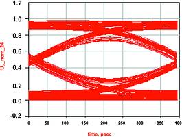
Appropriate manufacturing tolerances were also taken into account in all the simulations. These were assumed to be ±2% for SMD resistors, ±15% for on-chip resistors and ±5% for conducting strip widths. The following parameters were analysed for each simulation: S parameter in the frequency range (S11, S21), impedance values across the entire system, eye diagrams for data transmissions with 2,5 and 5,0 Gbps.
Results
The following fundamental results can be summarised from the extensive simulations. Generally speaking, the new ERmet ZD connectors permit the transmission of differential signals with data rates of 5 Gbps and above (Figure 5). However, during system analysis, all relevant parameters such as the connection method (SMT or pressfit technology), the circuit board material and the layout of the transmission lines on the backplane (width and length, conductor strip connections, termination resistance) must be taken into consideration.
In addition to the connectors, the choice of board material is decisive for optimised system design. The simulations were carried out using both FR4 and Rogers 4350. FR4 has a dielectric constant of 4,5 compared with 3,5 in the Rogers material. However, the essential difference lies in the dielectric loss factor, which in Rogers 4350 at 0,004 is lower by a factor of five than in the FR4 material. If one compares the representation of the S parameter and the eye diagrams for the two circuit board materials, the differences become evident in the substantially higher attenuation with the FR4 material.
Conclusions
Differential signal transmission permits the design of systems with data rates of several Gbps. With such high data rates, the connectors must be designed so that impedance discontinuities are kept as low as possible. In addition, the mutual electromagnetic shielding between the differential signal pairs must be highly optimised. The new ERmet ZD connector system meets these requirements. However, as system analysis shows, the circuit board material, the connection technology and board layout must also be optimised for the system requirements. The use of low-loss circuit board materials, reduced track lengths and wider tracks contribute to a reduction in dielectric as well as skin effect losses.
| Tel: | +27 11 608 3001 |
| Email: | [email protected] |
| www: | www.actum.co.za |
| Articles: | More information and articles about Actum |


© Technews Publishing (Pty) Ltd | All Rights Reserved
 printer friendly version