


The days of simple car radios using large telescope antennas are over. Nowadays cars are equipped with full featured infotainment or multimedia systems.
While the AM/FM radio is still a part of the system, features like digital audio broadcasting (DAB), HDTV, satellite radio, integrated cellphones, CD/DVD/MP3 players, GPS navigation or video game systems are added.
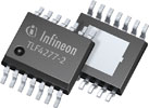
AM/FM, DAB and satellite signals are received by active antenna systems with stubby, shark fin or windshield antennas. As car infotainment units have become more complex, the number of active antenna systems has grown as well. Sensitive circuitry like low-noise amplifiers (LNAs) in these systems requires a stable power supply, protection and isolation from the harsh automotive environment, as well as monitoring and diagnostic functions to provide antenna status. Infineon Technologies’ new TLF4277-2 (Figure 1) is designed to reliably supply active antennas in car infotainment applications.
An active antenna is one that contains active electronic components. In contrast with passive antennas, this allows the construction of antennas of limited size and/or wide frequency range. Power for the active components may be supplied by batteries, a filtered power supply, or through the signal feeder itself (phantom power).
The TLF4277-2 low dropout voltage regulator provides the related voltage to the active antenna. The adjustable output voltage (5 V to 12 V) makes it capable of supplying the majority of standard active antennas, such as FM/AM, DAB, XM or Sirius.
The chip protects both the antenna and itself in this demanding electrical environment, while providing a stable output voltage. It also protects active antenna supply circuitry in the event of a short circuit within the antenna supply with an adjustable current limit.
Thermal conditions in automotive environments are equally challenging, requiring the supply to be stable over the automotive temperature range of -40°C to 150°C with robust over-temperature protection. In addition to these protection requirements, the TLF4277-2 simplifies the gathering of diagnostic information required to report antenna status.
New generation with enhanced features
The TLETLF4277-2 is the second generation of the TLETLF4277 family which was successfully implemented in various active antenna applications and shipped in high volume. The new voltage regulator provides several enhancements like better accuracy (of VQ and current monitor), higher output current and less external components.
The IC is a monolithic integrated low drop-out voltage regulator (Figure 2) capable of supplying loads up to 300 mA. For an input voltage up to 40 V it provides an adjustable output voltage in a range from 5 V up to 12 V. The integrated current monitor function is a unique feature that provides diagnostic and system protection functionality. Fault conditions such as over-temperature and output over-voltage are monitored and indicated at the current sense output.
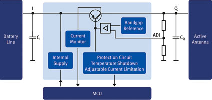
The maximum output current limit of the device is adjustable to provide additional protection to the connected load. Via the enable function the IC can be disabled to lower power consumption. Other features are a low dropout voltage (typically 100 mV) and very low power consumption (150 μA typical at 25°C).
Accurate antenna status monitoring is provided by very accurate current sense, with continuous monitoring of the load. Compared to other solutions with current sense accuracy in the range of 10% to 30%, the TLF4277-2 provides accuracy (current monitor factor) as tight as 5% across the full range of output current.
Compared to previous solutions the output voltage tolerance is also improved (2% compared to 3% - 5%). The adjustable maximum current limit in the range of 10 mA to 300 mA improves amplifier lifetime. The digital status output signal shows if one or more of the monitored protection functions (over-current, over-voltage or temperature shutdown) is activated.
The TLF4277-2 needs few external components, reducing required printed circuit board space. Furthermore, the fact that no external shunt is needed results in optimised system costs. Reduced component count is a critical aspect as most infotainment applications in cars are implemented on expensive multilayer boards; this also leads to higher reliability (better FIT rate). The IC enables a faster reaction time for the microcontroller in case of error compared to previous solutions, with an error flag that can be used to improve system reliability.
Principal function of the voltage regulator
The output voltage (VQ) is controlled by comparing the feedback voltage (VADJ) to an internal reference voltage and driving a PNP pass transistor accordingly. The control loop’s stability depends on the output capacitor CQ, the output series resistivity ESR, the load current and the chip temperature.
For stable operation a ceramic output capacitor with an ESR range from 1 mΩ to 10 Ω and only 1 μF is needed. The output capacitor may need to be sized larger to buffer load transients. An input capacitor is not needed for control loop stability, but is recommended to buffer line influences.
Protection circuitry prevents the IC as well as the application from destruction in case of catastrophic events. The integrated safeguards consist of output current limitation, reverse polarity and short circuit protection, as well as thermal shutdown in case of over-temperature.
The thermal shutdown circuit prevents the IC from immediate destruction under fault conditions (e.g. output continuously short circuited) by switching off the power stage. After the chip has cooled down, the regulator restarts. This leads to a cycling behaviour of the output voltage until the fault is removed.
The TLF4277-2 permits a negative supply voltage; however, this causes several small currents to flow into the IC, increasing its junction temperature. This reverse current has to be considered for the thermal design, considering that the thermal protection circuit is not operating under reverse polarity.
The output voltage of the chip can be adjusted between 5 V and 12 V by an external output voltage divider, closing the control loop to the voltage adjust pin.
The voltage at this pin is compared to the internal reference of typical 1,19 V in an error amplifier, enabling control of the output voltage.
Current and protection monitor
The TLF4277-2 provides a set of advanced monitor functions (Figure 3). The current flowing out of the power stage can be monitored at the CSO output. In addition the current limit can be adjusted via an external resistor.
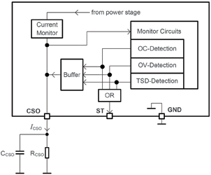
Events of the implemented protection functions are reported through dedicated voltage levels at the CSO output. This information can be processed by an external microcontroller for system analysis and failure identification. The monitored events are over-current, over-voltage and temperature shutdown. All three fault conditions are routed to a digital output pin.
For more information contact Davis Moodley, Infineon Technologies, +27 (0)11 706 6099, davis-moodley.external@infineon.com, www.infineon.com






© Technews Publishing (Pty) Ltd | All Rights Reserved
 printer friendly version