


The Universal Serial Bus (USB) is the most used computer interface in the world. It started as an expansion bus for personal computers, but has proliferated quickly due to its flexibility, performance and hot-plug capability.
Most portable electronic devices that require PC connectivity use USB for file transfers. These include MP3 players, digital cameras, mobile phones and tablets.
Since a standard USB bus downstream port can provide at least 500 mA (USB 2.0) or 900 mA (USB 3.0) of current, it was convenient to use it for charging these devices. But if this current limit was increased, the charging could be made more efficient. This can be done using the Microchip USB2534 hub controller with RapidCharge.
If the current required exceeds the limits then both the charging device and the charging port must follow a protocol to enable battery charging. A downstream battery charging port is responsible for providing the proper handshake signalling to the charging device to indicate that it is attached to a charging port and can draw currents above the standard USB limits.
The proper signalling varies depending on the portable device. Some portable devices follow USB-IF BC1.2 protocols, but there is an installed base of devices that use proprietary handshake protocols, also known as legacy modes, for battery charging.
Legacy devices support some form of battery charging detection intended for use with a dedicated charger. Some of these chargers short D+ to D- directly or connect them through a series resistor. For charger detection, some legacy devices assert a voltage on D+ by connecting a pull-up and then sensing a voltage on D-. If a positive voltage is detected, the device can assume it is plugged into a dedicated charger and not a standard USB port. Other devices pull down one data line while pulling up the other. Once the device detects a charger by the presence of a voltage on D-, it can start charging from the Vbus connection at current levels that exceeds the USB specification.
Other legacy devices rely on the charger to drive fixed voltages (more than 1 V) on the D+ and D- data lines. These are referred to as SE1 chargers. If these voltages are sensed by the charging device, the device assumes it is plugged into a dedicated charger and starts charging. A standard USB downstream port would not present these fixed voltages on the D+ and D- lines.
Charger detection
The portable device is responsible for charger detection and Figure 1 shows the hardware that is needed. There are five functional blocks: Vbus detect, data contact detect, primary detection, secondary detection and ACA detection.
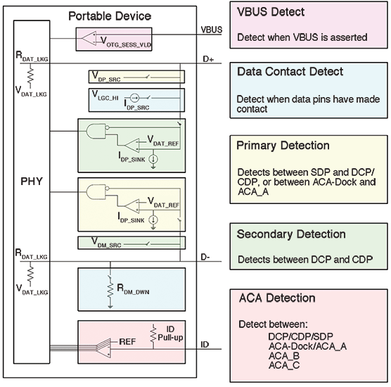
A portable device includes a session valid comparator. Vbus has to be above the threshold voltage before the charger detection is initiated. This is shown as VOTG_SESS_VLD on the diagram.
Data contact detect is an optional block used to confirm that the data lines made contact during attachment. A current source on D+ and a pull-down resistor on D- are turned on. If the D+ line goes low this indicates that data lines are attached to a charging port or a standard port and the logic proceeds to start primary detection. A timeout circuit is needed to ensure that primary detection starts after a set time after attachment in case contact is not detected or the data contact detect block is not present.
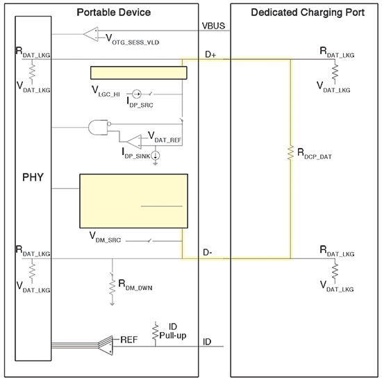
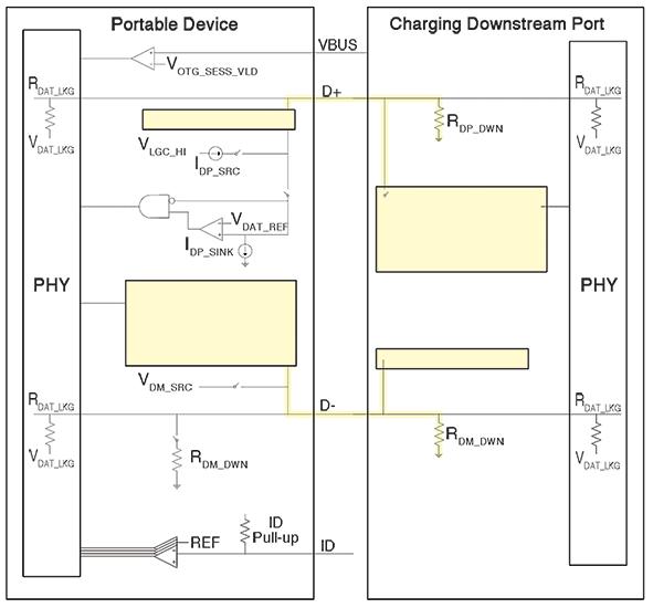
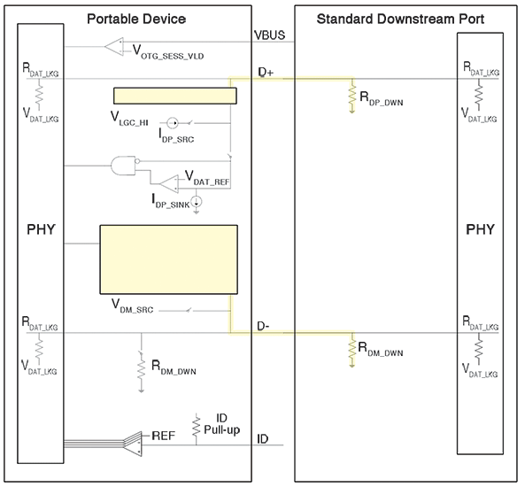
A portable device is needed to implement primary detection, which is used to distinguish between a standard downstream port (SDP) and a charging port. Figure 2 shows what happens when the device is connected to a dedicated charging port (DCP), Figure 3 when it is connected to a charging downstream port (CDP) and Figure 4 when it is connected to an SDP.
Secondary detection is used to distinguish between a DCP and a CDP. If a portable device is ready for enumeration within a set time after Vbus detection, it can bypass secondary detection, otherwise it needs to implement it. Only portable devices with a USB Micro-AB connector can support ACA detection, and thus it is optional. Detection is done by measuring the resistance of the ID pin.
Battery charging
The Microchip USB2534 hub controller includes RapidCharge technology for providing the proper handshake signalling to portable devices on downstream ports to enable battery charging. It also includes the capability for USB upstream battery charger detection.
To charge most portable devices it is necessary to provide the proper handshake signals for legacy chargers, SE1 chargers, chargers compliant with Chinese Telecommunications Industry battery charger specification YD/T 1591-2009 and BC1.2 compliant devices. The hub controller includes all these protocols to implement complete battery charging supporting devices from Apple, Samsung and others.
If a USB downstream port is configured to support battery charging, the port is a CDP if it can enumerate the device or DCP if it cannot enumerate a device. If the port is not configured to support battery charging, the port is an SDP. The downstream ports can be enabled for battery charging by adding a pull-up resistor (10 kΩ) on the battery charging configuration strap for the corresponding port. These straps are sampled at reset and if they are sampled high the corresponding port is enabled for battery charging.
Battery charging can also be enabled by use of the battery charging configuration registers that reside in the USB2534. These registers are used by the internal ROM firmware to configure the battery charging functionality for each port, and can be modified by a configuration programmed in the one-time programmable (OTP) memory using the ProTouch programming tool.
ProTouch is a Microchip developed tool for configuration and programming of the USB2534 hub controller. It can be used for development and prototyping where a single part is programmed or for multiple parts in a manufacturing environment.
When there is no upstream Vbus, and consequently no USB host connected on the upstream port, the downstream battery charging enabled ports will operate as DCP ports. The battery charging enabled ports will exit this mode if the upstream port has a host connection. DCP mode will also be entered if the USB2534 is suspended and remote wakeup is disabled.
In DCP mode battery charging, the port will attempt to handshake with and identify the BC capable device. In DCP mode the device always starts in SE1 mode. It cannot detect that an SE1 device is attached, but can detect that a non-SE1 device is attached when the device toggles DM or DP.
Upon entering RapidCharge mode, the USB2534 goes into SE1 charging mode and the port presents the SE1 voltage levels. If an SE1 device is attached, it will passively detect the SE1 levels and begin to charge. The DCP will not be able to detect the presence of the SE1 device. The port remains in SE1 charging mode while the SE1 PD is charging.
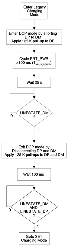
If a BC 1.2 device is attached, its current is strong enough to pull the D- line low. Likewise, legacy charging devices have been observed to pull the D- line low when attached. To accommodate this, the downstream port transitions to legacy charging mode if the classic D- line state is detected as low. The D- line state is de-bounced to avoid false detects from device plug-ins. Legacy charging mode is shown in Figure 5.
The battery charging enabled ports will exit DCP mode and enter CDP mode if the upstream port gets a host connection. On detection of the USB host set address command, any BC enabled port will be turned off for at least 250 ms before it can be turned on to allow the port power to decay. If the host sends a command to turn on the port power, the command will be delayed appropriately. If the command is received after the timer has expired, it will be executed immediately.
An external MCU can override the automatic charger detection sequence by modifying the SMBus runtime battery charging registers. Because the start of battery charging detection is set to occur by default, the MCU must write to the battery charging control register or the configuration interlock register to disable the automatic sequence before the sequence begins. If the automatic sequence is disabled, the MCU can still initiate it manually.
Conclusion
USB battery charging provides a convenient mechanism for recharging batteries on portable devices such as mobile phones and tablets. The USB-IF published the BC1.2 battery charging specification to help standardise the protocols used between chargers and charging devices to safely enable battery charging.
The Microchip USB2534 hub controller with RapidCharge provides battery charging protocols that include legacy, SE1, Chinese Telecommunications Industry YD/T 1591-2009 and USB-IF BC1.2 to implement battery charging supporting devices from Apple, Samsung and most other devices. The hub controller also supports battery charger detection for use in portable devices that require USB charger detection capability.
| Email: | willem.hijbeek@tempetech.co.za |
| www: | |
| Articles: | More information and articles about Tempe Technologies |






© Technews Publishing (Pty) Ltd | All Rights Reserved
 printer friendly version