


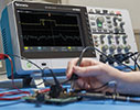
Basic oscilloscopes are used as windows into signals for troubleshooting circuits or checking signal quality.
They generally come with bandwidths from around 50 MHz to 200 MHz and are found in almost every design lab, education lab, service centre and manufacturing cell.
Whether one is buying a new scope every month or every five years, this article will give a quick overview of the key factors that determine the
suitability of a basic oscilloscope to the job at hand.
The digital storage oscilloscope
Oscilloscopes are the basic tool for anyone designing, manufacturing or repairing electronic equipment. A digital storage oscilloscope (DSO, on which this article concentrates) acquires and stores waveforms. The waveforms show a signal’s voltage and frequency, whether the signal is distorted, timing between signals, how much of a signal is noise, and much, much more.
#1 Bandwidth
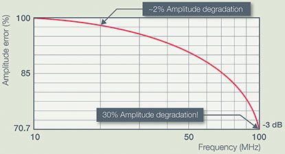
System bandwidth (see Figure 1) determines an oscilloscope’s ability to measure an analog signal. Specifically it determines the maximum frequency that the instrument can accurately measure. Bandwidth is also a key determining factor in price.
Determine what you need
For example, a 100 MHz oscilloscope is usually guaranteed to have less than 30% attenuation at 100 MHz. To ensure better than 2% amplitude accuracy, inputs should be lower than 20 MHz. For digital signals, measuring rise and fall time is key. Bandwidth, along with sample rate, determines the smallest rise-time that an oscilloscope can measure.
The probe and oscilloscope form a measurement system that has an overall bandwidth. Using a low-bandwidth probe will lower the overall bandwidth so be sure to use probes that are matched to the scope.
Consider a higher-performance oscilloscope
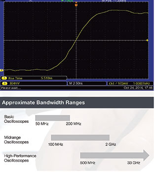
Basic oscilloscopes usually range from 50 MHz to 200 MHz. If more bandwidth is needed, higher-performance instruments are available to cover from 350 MHz up to tens of gigahertz.
#2 Sample rate
The sample rate of an oscilloscope is similar to the frame rate of a movie camera. It determines how much waveform detail the scope can capture.
Determine what you need
Sample rate (samples per second, Sps) is how often an oscilloscope samples the signal. Again, the ‘five times rule’ is recommended, i.e., use a sample rate of at least five times the circuit’s highest frequency component, as illustrated in Figure 2. Most basic scopes have a (maximum) sample rate of 1 to 2 GSps.
It is important to remember that basic scopes have bandwidth up to 200 MHz, so scope designers usually build in 5 to 10 times oversampling at maximum bandwidth. The faster the sampling (see Figure 3), the less information will be lost and the better the scope will represent the signal under test, but the faster the memory will be filled up too, which limits the time that can be captured.
To capture glitches you need speed
Nyquist said that a signal must be sampled at least twice as fast as its highest frequency component to accurately reconstruct it and avoid aliasing (undersampling). Nyquist however is an absolute minimum – it applies only to sine waves, and assumes a continuous signal. Glitches are by definition not continuous, and sampling at only twice the rate of the highest frequency component is not enough.
Consider a higher-performance oscilloscope
Most entry-level scopes have a maximum sample rate of 1 to 2 GSps. When working at frequencies above 200 MHz, a higher-performance instrument is recommended.
#3 Enough input channels – and the right ones
Digital oscilloscopes sample analog channels to store and display them. In general, the more channels the better, although adding channels adds to the price.
Determine what you need
Whether to select two or four analog channels depends on the application. Two channels allow comparison of a component’s input to its output, for example. Four analog channels let more signals be compared, and provides more flexibility to combine channels mathematically (multiplying to get power, or subtracting for differential signals, for example.
A mixed-signal oscilloscope adds digital timing channels, which indicate high or low states and can be displayed together as a bus waveform. Whatever is chosen, all channels should have good range, linearity, gain accuracy, flatness and resistance to static discharge.
Some instruments share the sampling system between channels to save money, but beware: the number of channels that are turned on can reduce the sample rate. The more time-correlated analog and digital channels a scope has, the more points in a circuit can be measured at the same time and the easier it is to decode a wide parallel bus, for instance.
Consider a higher-performance oscilloscope
The latest mixed domain oscilloscopes add a built-in spectrum analyser with a dedicated RF input for making measurements in the frequency domain. Some oscilloscopes also include built-in function generators. Some oscilloscopes offer isolated input channels to simplify floating measurements. Unlike ground referenced oscilloscopes, the input connector shells are isolated from each other and from earth ground.
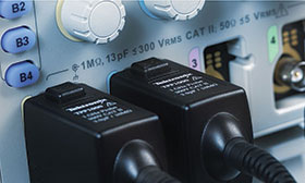
#4 Compatible probes
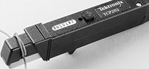
Good measurements begin at the probe tip. The scope and probe work together as a system, so be sure to consider probes (Figure 4) when selecting an oscilloscope.
During measurements probes actually become a part of the circuit, introducing resistive, capacitive and inductive loading that alters the measurement. To minimise the effect it’s best to use probes that are designed for use with the scope.
Select passive probes that have sufficient bandwidth; the probe’s bandwidth should match that of the oscilloscope. A broad range of compatible probes will allow a scope to be used in more applications. Check to see what’s available for the scope before buying.
Use the right probe for the job
Passive probes with 10x attenuation present a controlled impedance and capacitance to a circuit, and are suitable for most ground-referenced measurements. They are included with most oscilloscopes, and one will be needed for each input channel.
High-voltage differential probes allow a ground-referenced oscilloscope to take safe, accurate floating and differential measurements – every lab should have at least one.
Logic probes deliver digital signals to the front end of a mixed-signal oscilloscope. They include ‘flying leads’ with accessories designed to connect to small test points on a circuit board.
Adding a current probe enables the scope to measure current, of course, but it also enables it to calculate and display instantaneous power.
Consider a higher-performance oscilloscope
Analysing high-speed communications signals requires high-bandwidth active probes and will require an oscilloscope with hundreds of MHz, or even GHz of bandwidth.
#5 Triggering
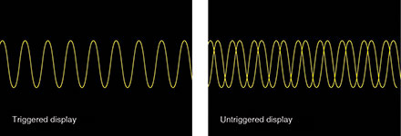
As illustrated in Figure 5, triggering gives a stable display and allows one to zero in on specific parts of complex waveforms.
Determine what you need
All oscilloscopes provide edge triggering, and most offer pulse width triggering. To acquire anomalies and make best use of the scope’s record length, look for a scope that offers advanced triggering on more challenging signals. The wider the range of trigger options available, the more versatile the scope (and the faster one can get to the root cause of a problem).
The types of triggering options available include digital/pulse triggers (pulse width, runt pulse, rise/fall time, setup-and-hold); logic triggering; serial data triggers (embedded system designs use both serial – I²C, SPI, CAN/ LIN etc. – and parallel buses; and video triggering.
Triggering enables the isolation of a group of waveforms to see what is going wrong.
Specialised triggers can respond to specific conditions in the incoming signal, making it easy to detect, for example, a pulse that is narrower than it should be.
Consider a higher-performance oscilloscope
Sequence triggering can help capture more elusive signal events. It is sometimes called ‘A then B’ triggering and can be used to acquire based on a multi-channel sequence. Triggering on data being transferred on high-speed versions of systems buses like USB and Ethernet requires higher bandwidth and sample rate than is available on basic oscilloscopes.
#6 Record length
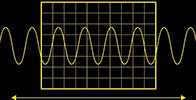
Record length is the number of points in a complete waveform record. A scope can store only a limited number of samples so, in general, the greater the record length the better (see Figure 6).
Determine what you need
Time captured = record length/sample rate.
So, with a record length of 1 Mpoints and a sample rate of 250 MSps, the oscilloscope will capture 4 ms.
Today’s scopes allow the record length to be selected to optimise the level of detail needed for the application. A good basic scope will store over 2000 points, which is more than enough for a stable sine-wave signal (needing perhaps 500 points). But to find the causes of timing anomalies in a complex digital data stream, 1 Mpoints or more should be considered.
Zoom & pan allows one to zoom in on an event of interest, and pan the area backwards and forwards in time. Search & mark enables searching through the entire acquisition and automatically marking every occurrence of a user-specified event.
Oscilloscopes with record lengths in the millions of points can show many screens worth of signal activity, essential for examining complex waveforms. Long record length means a long time window can be seen, and lets the user zoom in to see signal detail with good resolution.
Consider a higher-performance oscilloscope
Oscilloscopes are available with millions of points of data and manually searching for events can become impractical. Some scopes include search functions to help search long records for specific events.
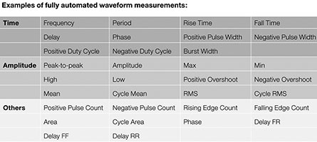
#7 Automated measurements and analysis
Automated waveform measurements (Figure 7) make it easier to obtain accurate numerical readings.
Determine what you need
Most scopes offer front-panel buttons and/or screen-based menus to take accurate automated measurements. Basic choices on most scopes include amplitude, period and rise/fall time. Many digital scopes also provide mean and RMS calculations, duty cycle, and other math operations.
Measurement ‘gating’ allows the user to determine the section of the waveform used to calculate measurements. Channel math functions perform addition, subtraction and multiplication of waveforms.
Waveform multiplication can be used to multiply voltage and current to get power, while subtraction can be used to approximate a differential measurement.
A Fast Fourier Transform (FFT) feature allows one to see the frequency spectrum of an acquired waveform. Basic oscilloscopes often include an FFT function – useful for trying to determine the source of noise, for example.
Consider a higher-performance oscilloscope
A basic oscilloscope does not have enough dynamic range to look at small RF signals like a spectrum analyser can. Mixed domain oscilloscopes, on the other hand, have dedicated spectrum analyser inputs that allow small RF signals to be clearly seen.
#8 Easy operation
Oscilloscopes should be easy to operate, even for occasional users (see Figure 8). The user interface is a large part of the ‘time to answer’ calculation.
Determine what you need
The scope should be responsive, reacting quickly to changing events, and frequently-used adjustments should have dedicated knobs, with autoset and/or default buttons making for instant setup. A relatively new development in the world of scopes is the ability to display lab procedures and tips right on the display. It also provides report-generating facilities to help students get more out of their labs.
Oscilloscopes should provide different ways to operate the instrument. Built-in help can provide a convenient, built-in reference manual, while smart menus give easy access to multifunction, context-sensitive commands. There should be support for the user’s own language, including the menu system, built-in help, manuals and ideally front-panel overlays.
#9 Connectivity
Connecting a scope to a computer directly (see Figure 9) or transferring data via portable media allows advanced analysis, and simplifies documenting and sharing results.
Determine what you need
To aid in report generation, many oscilloscopes can produce JPG, BMP or PNG files that can easily be incorporated. Compatibility with third-party analysis and documentation software should be considered, such as the instrument’s ability to produce CSV files for offline analysis.
Look for a complete, well-written programmer’s manual and check for programming examples. Many scopes come with software or make it available for download to help capture screens, collect waveform data, or save instrument setups. One should see what’s available for their favourite programming environment, since readily available drivers can save significant time and effort.
If it is planned to build the scope into a rack system at some point, check to make sure a rack mount kit is available. Some scopes offer a VGA output, to allow connection of an external monitor for easier group viewing. Wi-Fi support enables communication with the scope without having to connect cables.
#10 Serial bus decoding
Most system-level (computer to computer) communication is transferred over serial data links. Even on today’s circuit boards, much of the chip-to-chip data is transferred over serial buses.
Determine what you need
Some scopes are able to decode serial buses and display data time-correlated with other waveforms. Automatic decoding is much less time-consuming and less error-prone than hand decoding.
In addition to decoding, some scopes provide the ability to trigger and search for serial data values. These capabilities help speed troubleshooting.
Decoded chip-to-chip buses such as I²C and SPI can help provide a more complete view of a board. Decoded RS-232/UART or
CAN/LIN can provide a view of system-level communications. There are generally more serial buses supported on higher performance scopes. For example, higher-speed buses like USB and Ethernet require higher bandwidth and sample rate than is usually available on basic oscilloscopes.
#11 Support: the X factor
After studying all the specs and features, some time should be taken to look into the after-sales support that can be expected. Important factors to look for include a comprehensive manufacturer’s web site in the correct language; customer support via email, online chat or phone; a broad network of distributors; downloadable manuals; a reputable and easily accessible repair and calibration organisation; application notes to help understand technology and learn about specific measurements; and software and drivers.
Many of these support avenues can be used to help with the research phase, too. Taking advantage of these support resources during the selection process will help one avoid post-purchase surprises later on.
| Tel: | +27 10 595 1821 |
| Email: | [email protected] |
| www: | www.comtest.co.za |
| Articles: | More information and articles about Comtest |


© Technews Publishing (Pty) Ltd | All Rights Reserved
 printer friendly version