


Since the introduction of lead-free alloys, the composition of solder paste chemistries has changed. More and varied components have been added to meet the higher temperature requirements of lead-free reflow soldering. Due to the different chemistries, the composition of the flux residues has changed as well over the years. Filter systems that were effective in the past may perform poorly today.
Additionally, PCB assemblies have undergone a continuous trend towards miniaturisation of PCB, components and SMD pad dimensions, resulting in higher density of solder joints per square inch, and consequently higher concentrations of reflow-generated contaminants.
The risk of oven contamination with reflow residues also increases where pin-in-paste reflow replaces traditional wave or selective soldering applications for through-hole components. Miniaturisation has also meant smaller alloy powder particle size in solder paste, with a higher flux content of the paste needed to minimise potential oxidation of the solder powder.
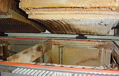
Traditional flux management systems that were successful for SnPb paste used heat exchangers to condense flux residues. These tacky residues could then be removed and additional filters were able to clean the gas properly. Every PCB assembly loses, on average, 0,25 grams of weight in the oven. Solder paste is 10% flux, of which approximately 50% remains on the board after soldering. A high-volume SMT line operating 24/7 will be contaminated with approximately 2 kg per week.
Figure 2 plots the results of thermogravimetric analysis (TGA) used to characterise the evaporation of four commonly used lead-free solder pastes in a 9-zone reflow oven, using a four minute lead-free reflow profile. The higher the values the more evaporation in that zone.
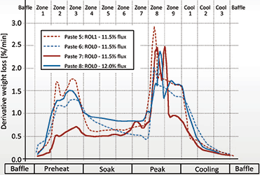
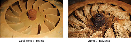
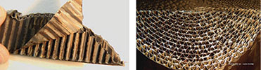
Solvents evaporate in zones 2 and 3 where activators, rosins and other chemicals show up in the peak zones when the solder paste is above the liquidous point of the SAC305. Different zones have different contamination because different chemistry is evaporating. Also in the cool zone some chemicals are still active, contaminating all cold areas where condensation takes place. This is partially illustrated by the two photographs in Figure 3.
Reflow exhaust gas typically contains a variety of organic compounds from solder paste, board material, solder mask and components. These volatile organic compounds need to be eliminated. To investigate further, an experiment was set up to find absorbers or catalysts to remove or convert the organic vapours generated when printed circuit boards are soldered in a reflow oven.
The experiment covered three phases:
1. Evaluate the efficiency of adsorbers and catalysts in a lab environment.
2. Design and implement a prototype in a reflow oven and define the feasibility of a catalyst system.
3. Implement catalyst concept in a production line and define efficiency in a real production environment.
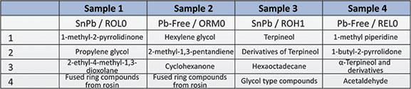
A specific gas chromatography/mass spectrometry (GC/MS) was used to identify volatile organic compounds present in the solder paste fluxes. Flux paste was held at 185°C for 30 minutes in a sealed vial. The sample was then taken from the vial headspace and injected into GC/MS. The temperature of 185°C was selected because of the reflow profile; this corresponds to soak temperatures and places where the gasses are exhausted out of the oven. The compounds in Table 1 were found in four samples.
Phase 1
A laboratory method was developed and a catalytic converter built to evaluate the efficiency of adsorbers and catalysts to remove or convert the organic vapours generated when solder flux is heated in a reflow oven.
There are two potential techniques that require further investigation since both methods crack the large molecules of the organics from solder paste, solder mask, component gasses and chain grease. These techniques are pyrolysis, the decomposition of organic material at elevated temperatures in the absence of oxygen, and thermal oxidation, which converts organic vapours to carbon dioxide and water in the presence of oxygen. Pyrolysis is an endothermic reaction, while thermal oxidation is exothermic and happens at much lower temperatures; both processes produce char residues.
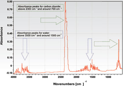
The sample of the flux paste was heated in the TGA at 10°C/min from room temperature to 300°C. The vapour generated by the flux paste in the TGA was carried to a heated converter by the carrier gas (nitrogen or air at a flow rate of 50 ml/min). The catalyst sample was heated at either 185°C or 225°C. The gasses then flowed into the gas analyser (FT-IR) where their chemical identities were determined.
Conclusions
When the adsorber is held at 225°C, no pyrolysis takes place; the vapours are either adsorbed by the material or pass through. Resulting FT-IR signals associated with glycol ethers (tripropylene glycol) were observed, and peaks associated with carbon dioxide, water, carbon monoxide and short chain hydrocarbons were identified at 500°C. The formation of black char on the surface of the adsorber also indicated that pyrolysis was taking place.
The composition of the vapour did not have an impact on the efficiency of the catalyst. The catalyst with the thicker layer and platinum group metals performed well in both nitrogen and air environments. For this catalyst, no organic vapours were detected with FT-IR at temperatures in excess of 185°C.
Phase 2
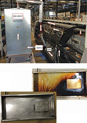
For the second phase of the tests, a large catalyst module was installed in a reflow oven between the heating zones and the flux management system. Flux from solder paste was used in high volumes to accelerate oven contamination for enhanced study of cleaning performance. The target of the experiment was to define feasibility of a catalyst cleaning a reflow oven. The flux of two different solder pastes was evaporated in high volume in a reflow oven following a lead-free reflow profile.
The first tests were done without the catalyst. After processing 2 kg of flux (corresponding to 20 kg of solder paste) the gas filtration unit was inspected. After the experiment all parts were cleaned and the test was repeated with the catalyst between the oven exhaust and gas filtration unit. Remarkably, all parts of the filtration unit were clean after the same 2 kg of flux being processed; indicating that the catalyst is able to remove all vapours.
Conclusions
A catalyst to clean vapours in a reflow oven is feasible. The catalyst dimensions used in this instance were oversized and need to be modified. The target is to make different catalyst units for different heating zones, since contamination levels are not identical over the complete reflow process.
Phase 3
Phase 3 was the implementation of a prototype in a high-volume production line. This beta side test ran for six months and the prototype was changed compared to phase 2. In this oven, each zone had its own catalyst, and all heating zones were fitted with a catalyst and also a slot exhaust between the last peak and the first cool zone.
Adding a catalyst in the exhaust tube reduced the contamination of the cool zones. In fact, for some solder paste in the cool zones more than 10% of the evaporation takes place. In this oven the catalysts replaced the gas filtration unit. The process showed that for the preheat and soak zone, where temperatures are significantly lower than the 200°C degrees of the catalyst zone, temperatures and consistency were not affected.
Conclusions
Maintenance was reduced from 48 hours to only 10 hours per quarter, corresponding to a maintenance interval from two weeks (6-8 hours) to eight weeks (two hours). The heat exchanger of the first cool zone was removed to the bottom side to achieve the eight week maintenance interval. Nitrogen consumption was found to decrease by more than 20% due to nitrogen cleaning and reuse after the catalyst.
| Tel: | +27 11 609 1244 |
| Email: | [email protected] |
| www: | www.zetech.co.za |
| Articles: | More information and articles about ZETECH ONE |


© Technews Publishing (Pty) Ltd | All Rights Reserved
 printer friendly version