


Custom colour temperature lighting can be obtained by mixing the outputs of four individual white LEDs with different parameters. This can be used to build a dimmable lamp with a particular colour temperature or use a dynamic model that simulates an incandescent lamp whose colour temperature changes as it is dimmed.
The method can produce adjustable colour temperature lights using LEDs with known parameters as well as part of an automated setup to yield consistent lighting sources by measuring and calibrating unknown LEDs.
Colour temperature
The colour temperature of a light source is the temperature of a black body that radiates light that is close to the colour of the light source. To define the distance between two colours, a parametric way of defining colours is needed, such as the CIE 1931 xy colour space shown in Figure 1.
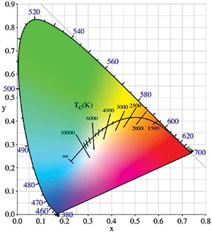
This colour space provides a simple mechanism that aids in colour mixing. Figure 1 also shows the Planckian locus defined by the possible colours of a black body as its temperature changes. The colours that this application tries to achieve lie on the Planckian locus.
The use case for this application is that the light source should be configured starting from a colour temperature. Planck’s Law describes the spectral power distribution of a black body of a specific temperature.
Light output
Since this application allows the configuration of the colour temperature, for consistency it would be desirable to have the same luminous flux range for any colour temperature chosen. This requires an extra normalisation step at the end of the colour mixing process to bring the maximum luminous flux to the same value for all possible colour temperatures.
Simulating an incandescent lamp requires an additional scaling factor for each colour temperature that needs to be computed. The chosen dimming mechanism models a black body whose power output is being controlled by a slider. This allow linking of the colour temperature with the luminous flux output in a natural manner, using the Stefan-Boltzmann Law, which states that the power radiated by a black body is proportional to the fourth power of its temperature.
For this application, the power is linearly varied between two arbitrary values and the corresponding temperature is bounded such that the colour temperatures can be rendered by the combination of LEDs. The coordinates in the CIE 1931 colour space that correspond to each temperature can be computed. The tri-stimulus value is proportional to the luminous flux for a given power emitted by the LED. Since the colour mixing algorithm produces relative intensities of the individual LEDs, this proportionality allows the computing of a scaling factor for each colour temperature that applies to all LEDs.
Mixing colours
Starting with a desired colour defined by its coordinates in the CIE 1931 colour space, the LED coordinates can be computed by first checking if the point lies within any of the triangles defined in the CIE 1931 colour space by the coordinates of three of the available LEDs. For all the triangles that contain the point, the individual LED contributions can be computed. It is then a matter of selecting the configuration that yields the maximum output for the chosen LED.
LED dimming values can be obtained from the flux values under the following conditions:
• Flux output approximated to be proportional to LED die current.
• All maximum luminous flux values are given at the same die current from LED measurements.
• Application only requires relative flux, with the colour defined by the proportions of fluxes, not their absolute values.
The last step is to scale these dimming values such that they lie between zero and the maximum value usable for the LED PWM. The values obtained after this step can be used to yield a constant luminous flux of any colour temperature. Further scaling can allow dimming on a single colour temperature, or these values can be used with the scaling factors computed to simulate an incandescent lamp.
Hardware
This application can use a modified Microchip lighting communications main board with the four Cree LEDs in Table 1 whose colour temperatures in the CIE 1931 colour space have been measured. The board can supply a maximum current through each LED on the order of 200 mA. The colour coordinates are assumed constant with varying currents and the luminous flux values proportional to the current.

Within these assumptions, the currents needed to mix the outputs from the LEDs into a particular colour temperature become easily computable. Using the four LEDs in Table 1, just a small subset of colours from the CIE 1931 colour space is available. This subset is the bounded area delimited by the coordinates of the individual LEDs. Figure 2 shows this area as the part of Plankian locus that can be reproduced using this step.
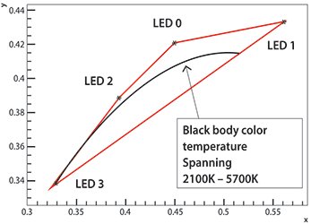
The application can reproduce light with the colour temperature between 2100 K and 5700 K with constant luminous flux. When simulating an incandescent light, each colour temperature is associated with a relative luminous flux. The colour temperature is dictated by the power of a virtual black body configured using the slider on the board.
The simulation of an incandescent lamp starts with the user selecting a slider position. This is translated into a colour temperature that can be used to pick both a scaling factor for all LEDs as well as individual scaling factors for each one.
The lamp has three modes of operation that the user can switch through:
1. Simulating an incandescent lamp: This both dims and changes the colour temperature according to the proposed model.
2. Constant luminous flux: This mode allows the user to pick a colour temperature using the slider while keeping the luminous flux at the maximum.
3. Dimming with constant colour temperature: This mode performs dimming while using the colour temperature chosen in the previous mode.
Conclusion
Controlling the individual LEDs to simulate an incandescent lamp requires a considerable amount of computation, which can be performed offline and stored in a Microchip PIC microcontroller at compile time. A PC application is available that computes these tables based on user configuration of the LED parameters. A screenshot is shown in Figure 3.
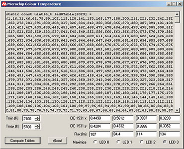
The application’s output consists of a number of constants grouped in six tables. These need to be copied from the application into the source file for the firmware. The application can be used with other LED parameters since these are fully adjustable, as is the colour temperature range.
| Email: | willem.hijbeek@tempetech.co.za |
| www: | |
| Articles: | More information and articles about Tempe Technologies |






© Technews Publishing (Pty) Ltd | All Rights Reserved
 printer friendly version