Differential signalling to clock faster, better control EMI, and accomplish long-haul serial transmission
10 April 2002
Telecoms, Datacoms, Wireless, IoT
Robert Hanson, American Seminars
As transmission speeds increase (10 gigabit SERDES, gigabit Ethernet, etc) there is greater need for high-speed serial transmission methods - usually Differential Signals (DS) for many companies. However, one must be aware that it has design restrictions that must be adhered to for successful design.
Here we look at the main requirements for DS, ie overcoming differential unbalance, controlling crosstalk, and providing the correct PCB layout.
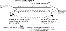
Figure 1. The ideal DS transmission
Differential unbalance
The ideal DS transmission is seen in Figure 1. If the two pathways are the same electrical length (EL), the return currents cancel. What would happen if they are not the same EL? The unbalance fraction is defined in Figure 1. When one edge arrives before the other, the return currents will not cancel until the second edge arrives. During this time, two detrimental effects will occur, a reflection on the line of the first arriving signal and crosstalk between the lines. Therefore, the layout personnel must be cognisant of these scenarios:
1. Propagation delay - (about 140 ps/in. outer layer, 180 ps/in. inner layer)
2. Vias - Each time a trace is disrupted by a via, the inductance of the total path is increased, thereby changing the EL.
3. Keep always - If one trace has to deviate around a pin, via, anti-pad, etc, the EL will be affected.
Figure 2. An example of noise (crosstalk) coupling into a differential pair
Crosstalk
Figure 2 defines an example of noise (crosstalk) coupling into a differential pair. Now, if the noise is only coupled to one and not the other, the receiver output data is useless.
Differential signals use two lines driven with complementary waveforms. A virtue of differential signals is that most noise sources couple roughly the same noise onto both lines. The differential receiver is designed to ignore signal components that are common to both lines (the common mode) while responding to the difference between the two lines (the differential mode), rejecting the coupled noise. A related benefit of differential signals is that the electromagnetic interference (EMI) generated by each line in the differential pair is largely cancelled by the other line.
PCB layout
There are three methods for laying out differential pairs: asymmetric; dual (broadside); side-by-side (edge).
Dual is very hard to accomplish due to accuracy of lamination process (x, y, and O errors among layers). The tradeoffs between dual and edge are:
* Side-by-side routing distances dual-distance and via length's electrical length.
* Three layer versus two layer lamination accuracy.
* Etching on 2 Cu planes versus 1 Cu plane.
Most companies will design using on-the-edge layout with the two sheets of Cu being ground planes. A major key to successful DS is careful planning of layout for EL and signals that are protected by the ground layers.
Robert Hanson will be delivering high-speed digital design seminars in South Africa during June. Contact [email protected], for further details.
Further reading:
The trends driving uptake of IoT Platform as a Service
Trinity IoT
Editor's Choice Telecoms, Datacoms, Wireless, IoT
IoT platforms, delivered as a service, are the key that will enable enterprises to leverage a number of growing trends within the IT space, and access a range of benefits that will help them grow their businesses.
Read more...
RF power amplifier
RF Design
Telecoms, Datacoms, Wireless, IoT
The ZHL-20M2G7025X+ from Mini-Circuits is a 32 W power amplifier that operates from 20 to 2700 MHz and delivers a saturated output power of +45 dBm.
Read more...
Introducing the Quectel EG800Z series
iCorp Technologies
Telecoms, Datacoms, Wireless, IoT
The EG800Z series is Quectel’s latest ultra-compact LTE Cat 1 bis module, designed to deliver reliable connectivity, low power consumption, and robust performance across a wide range of IoT applications.
Read more...
NeoMesh on LoRa
CST Electronics
Telecoms, Datacoms, Wireless, IoT
Thomas Steen Halkier, CEO of NeoCortec, recently gave a keynote speech where he spoke about “NeoMesh on LoRa: Bringing true mesh networking to the LoRa PHY”.
Read more...
Modules upgraded with Direct-to-Cell tech
iCorp Technologies
Telecoms, Datacoms, Wireless, IoT
Quectel Wireless Solutions has announced that several of its LTE modules are now available with Direct-to-Cell (D2C) functionality, enabling devices to seamlessly connect to satellite networks.
Read more...
USB/Ethernet smart RF power sensor
RF Design
Telecoms, Datacoms, Wireless, IoT
The PWR-18PWHS-RC from Mini-Circuits is an RF power sensor that operates from 50 MHz to 18 GHz and is designed to capture pulsed and trace modulated signals with very high data resolution.
Read more...
Tiny Bluetooth LE + 802.15 + NFC module
RF Design
Telecoms, Datacoms, Wireless, IoT
Unleashing enhanced processing power, expanded memory, and innovative peripherals, the BL54L15µ from Ezurio is the ultimate choice for small and low power connectivity.
Read more...
AI modules for edge intelligence
Otto Wireless Solutions
Telecoms, Datacoms, Wireless, IoT
SIMCom has introduced two new entry-level AI computing modules, the SIM8668 and SIM8666, designed to bring intelligent capabilities to lightweight, energy-efficient edge devices.
Read more...
High performance ISM antennas
iCorp Technologies
Telecoms, Datacoms, Wireless, IoT
Quectel Wireless Solutions has announced the launch of two new high performance ISM antennas, designed to meet the need for wireless communication in devices that operate in the industrial and commercial applications.
Read more...
Quad-band high-precision positioning module
iCorp Technologies
Telecoms, Datacoms, Wireless, IoT
Quectel Wireless Solutions has recently announced the launch of the LG680P, a multi-constellation, quad-band GNSS module designed to deliver high-precision positioning across a wide range of applications.
Read more...